Toyota Sienna Service Manual: Park / Neutral Position Switch Circuit
DESCRIPTION
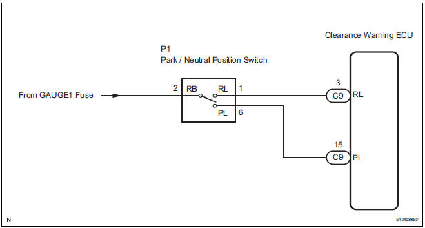
The clearance warning ECU receives the reverse or park position signal from the park / neutral position switch.
WIRING DIAGRAM
INSPECTION PROCEDURE
1 INSPECT CLEARANCE WARNING ECU
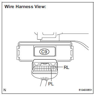
- Disconnect the C9 connector from the clearance warning ECU.
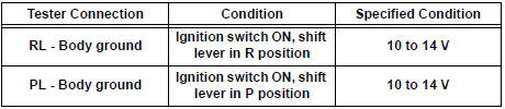
- Measure the voltage according to the value(s) in the table below.
Standard voltage
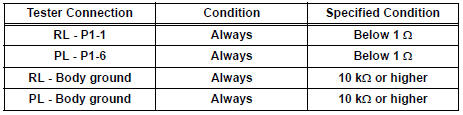
2 CHECK HARNESS AND CONNECTOR
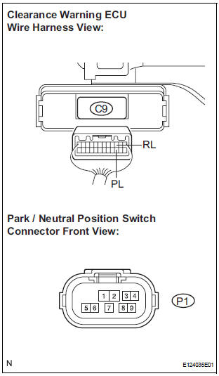
- Disconnect the connector from the park / neutral position switch.
- Measure the resistance according to the value(s) in the table below.
Standard resistance
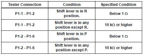
3 INSPECT PARK / NEUTRAL POSITION SWITCH
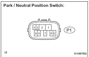
- Disconnect the park / neutral position switch connector P1.
- Measure the resistance according to the value(s) in the table below.
Standard resistance
REPAIR OR REPLACE HARNESS OR CONNECTOR
 Adjustment
1. ADJUST BUZZER VOLUME
Turn the knob on the clearance warning ECU to
adjust the volume.
...
 Speed Signal Circuit
DESCRIPTION
The clearance warning ECU receives the vehicle speed signal from the
combination meter.
HINT:
A voltage of 12 V or 5 V is output from each ECU and then input to
the combin ...
Other materials:
Front passenger occupant
classification system
Your vehicle is equipped with a front passenger occupant classification
system. This system detects the conditions of the front
passenger seat and activates or deactivates the devices for the
front passenger.
SRS warning light
Seat belt reminder light
“AIR BAG OFF” indicator light ...
Removal
1. REMOVE FRONT DOOR LOWER FRAME BRACKET GARNISH LH
2. REMOVE FRONT DOOR INSIDE HANDLE BEZEL PLUG LH
3. REMOVE POWER WINDOW REGULATOR MASTER SWITCH ASSEMBLY
4. REMOVE FRONT DOOR TRIM BOARD SUBASSEMBLY LH
5. REMOVE SEAT MEMORY SWITCH
Disengage the 4 claws and remove the seat
memor ...
Rear view monitor system precautions
Area displayed on screen
The rear view monitor system
displays an image of the view
from the bumper of the rear
area of the vehicle.
The image on the rear view monitor system can be adjusted.
The area displayed on the
screen may vary according to
vehicle orientation conditions.
...
