Toyota Sienna Service Manual: Steering Angle Sensor Circuit Malfunction
DTC C1231/31 Steering Angle Sensor Circuit Malfunction
DESCRIPTION
The steering angle sensor signal is sent to the skid control ECU through the CAN communication system.
When there is a malfunction in the communication, it will be detected by the
diagnosis function.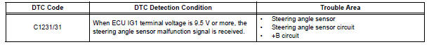
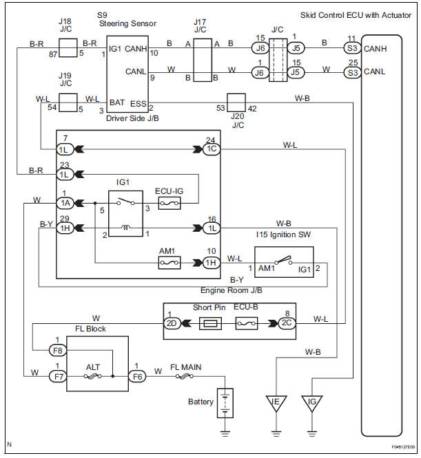
WIRING DIAGRAM
INSPECTION PROCEDURE
HINT:
- When U0073/94, U0100/65, U0123/62, U0124/95 or U0126/63 are output accompanied with C1231/ 31, inspect and repair the trouble areas indicated by U0073/94, U0100/65, U0123/62, U0124/95 or U0126/63 first.
- When the speed sensor or the yaw rate sensor has trouble. DTCs for the steering angle sensor may be output even when the steering angle sensor is normal. When DTCs for the speed sensor or yaw rate sensor are output accompanied with other DTCs for the steering angle sensor, inspect and repair the speed sensor and yaw rate sensor first, and the n inspect and repair the steering angle sensor.
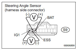
1 INSPECT STEERING ANGLE SENSOR
(a) Remove the steering wheel and the column lower cover.
(b) Disconnect the steering angle sensor connector.
(c) Turn the ignition switch to the ON position.
(d) Measure the voltage according to the value(s) in the table below.
Standard voltage 
(e) Measure the voltage according to the value(s) in the table below.
Standard voltage 
REPLACE STEERING ANGLE SENSOR
 SM Solenoid Circuit
DTC C1225/25 SM Solenoid Circuit
DESCRIPTION
This solenoid turns on when receiving signals the ECU and controls the
pressure acting on the wheel
cylinders to control the braking force.
WIRIN ...
 Stuck in Deceleration Sensor
DESCRIPTION
The yaw rate sensor and deceleration sensor signal is sent to the skid
control ECU through the CAN
communication system. When there is a malfunction in the communication, it will
...
Other materials:
Removal
1. PRECAUTION
HINT:
See page RS-1
2. DISCONNECT BATTERY NEGATIVE TERMINAL
Wait for 90 seconds after disconnecting the battery
terminal to prevent the airbag working.
3. PLACE FRONT WHEELS FACING STRAIGHT AHEAD
4. REMOVE STEERING WHEEL COVER LOWER NO.2
(See page RS-424)
5. REMOVE STEERING WH ...
Coolant Thermostat (Coolant Temperature Below Thermostat Regulating
Temperature)
HINT:
This DTC relates to the thermostat.
DESCRIPTION
This DTC is set when the Engine Coolant Temperature (ECT) does not reach 75°C
(167°F) despite
sufficient engine warm-up time.
MONITOR DESCRIPTION
The ECM estimates the ECT based on the starting temperature, engine loads,
a ...
Short to GND in Curtain Shield Squib RH Circuit
DTC B1162/81 Short to GND in Curtain Shield Squib RH Circuit
DESCRIPTION
The curtain shield squib RH circuit consists of the center airbag sensor
assembly and the curtain shield
airbag assembly RH.
The circuit instructs the SRS to deploy when deployment conditions are met.
DTC B1162/81 is ...
