Toyota Sienna Service Manual: Steering Pad Switch Circuit
DESCRIPTION
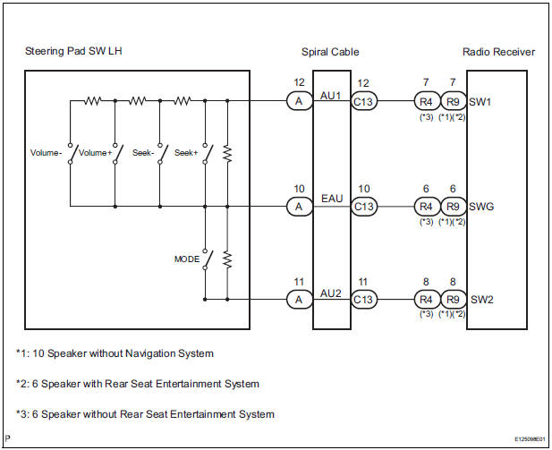
This circuit sends an operation signal from the steering pad switch to the radio receiver.
If there is an open in the circuit, the audio system cannot be operated using the steering pad switch.
If there is a short in the circuit, the same condition as that when the switch is continuously depressed occurs.
Therefore, the radio receiver cannot be operated using the steering pad switch, and also the radio receiver itself cannot function.
WIRING DIAGRAM
INSPECTION PROCEDURE
NOTICE: The vehicle is equipped with an SRS (Supplemental Restraint System) which includes components such as airbags. Before servicing (including removal or installation of parts), be sure to read the precautionary notice for the Supplemental Restraint System
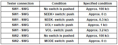
1 INSPECT RADIO RECEIVER
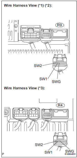
- Disconnect the radio receiver connector R4 or R9.
- Measure the resistance according to the value(s) in the table below.
Standard resistance
*1: 10 Speaker without Navigation System
*2: 6 Speaker with Rear Seat Entertainment System
*3: 6 Speaker without Rear Seat Entertainment System
PROCEED TO NEXT CIRCUIT INSPECTION SHOWN IN PROBLEM SYMPTOMS TABLE
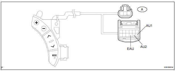
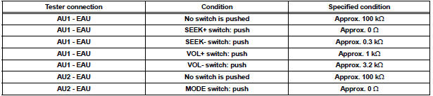
2 INSPECT STEERING PAD SWITCH ASSEMBLY
- Disconnect the steering pad switch LH connector.
- Measure the resistance according to the values in the table below.
Standard resistance
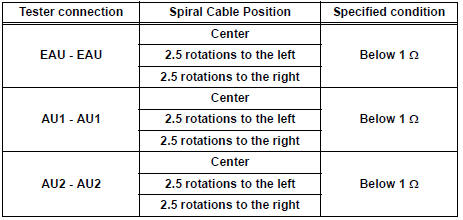
3 INSPECT SPIRAL CABLE
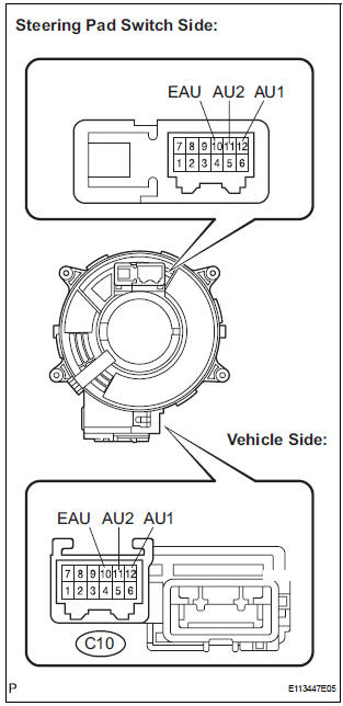
- Disconnect the steering pad switch and spiral cable connectors.
- Measure the resistance according to the value(s) in the table below.
Standard resistance
NOTICE: The spiral cable is an important part of the SRS airbag system. Incorrect removal or installation of the spiral cable may prevent the airbag from deploying. Be sure to read the page shown in the brackets
REPAIR OR REPLACE HARNESS OR CONNECTOR (SPIRAL CABLE - RADIO RECEIVER)
 Vehicle Speed Signal Circuit between Radio Receiver and Combination
Meter
Vehicle Speed Signal Circuit between Radio Receiver and Combination
Meter
DESCRIPTION
This circuit is necessary for the ASL (Auto Sound Leveliser) built into the
radio receiver.
Speed signals are received from the combination meter and used for the ASL.
The ASL fun ...
 Illumination Circuit
DESCRIPTION
Power is supplied to the radio receiver and steering pad switch illumination
when the light control switch is
in the TAIL or HEAD position.
WIRING DIAGRAM
INSPECTION PROCEDURE
N ...
Other materials:
Check for open circuit
(a) For an open circuit in the wire harness in Fig. 1, the resistance or
voltage, as described below.
(b) Check the resistance.
Check the resistance
Standard resistance (Fig. 2)
HINT:
Measure the resistance while lightly shaking the
wire harness vertically and horizontally. I ...
Installation
1. INSTALL REAR AXLE BEAM DAMPER
(a) Install the rear axle beam damper to the rear axle
beam assembly.
2. INSTALL REAR AXLE CARRIER BUSH LH
(a) Align the matchmarks on the axle beam assembly
with the 2 notches of a new bushing and temporarily
install the bushing to the rear axle beam assem ...
Linked mirror function when reversing (if equipped)
When the mirror select switch is in the L or R position, the outside rear
view mirrors will automatically angle downwards when the vehicle is
reversing in order to give a better view of the ground.
To disable this function, move the mirror select switch to the neutral
position (between L and R ...
