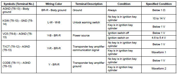
Toyota Sienna Service Manual: Terminals of ECU
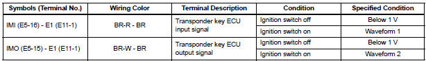
1. CHECK TRANSPONDER KEY AMPLIFIER
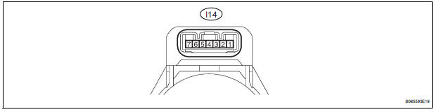
- Disconnect the I14 amplifier connector and measure the resistance between the terminal of the wire harness side connector and body ground.

If the result is not as specified, there may be a malfunction on the wire harness side.
- Reconnect the I14 amplifier connector and measure the resistance and voltage of each terminal of the connector
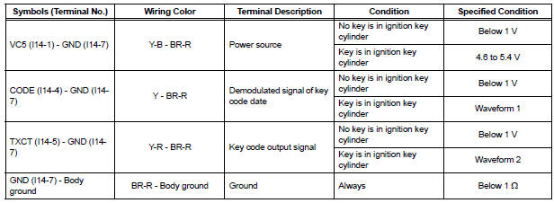
If the result is not as specified, the amplifier may have a malfunction.
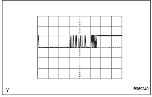
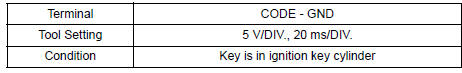
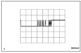
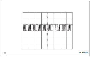
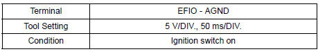
- Inspect using an oscilloscope.
- Waveform 1 (Reference):
- Waveform 2 (Reference):
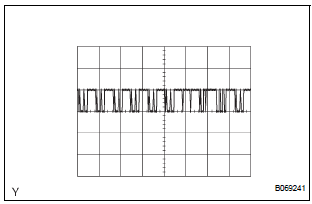
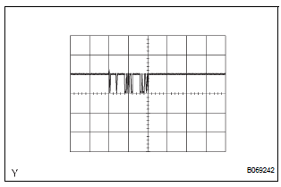
2. CHECK TRANSPONDER KEY ECU ASSEMBLY
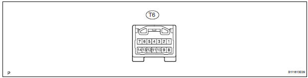
- Disconnect the T6 ECU connector and measure the resistance and voltage between each terminal of the wire harness side connector
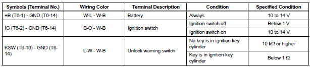
If the result is not as specified, there may be a malfunction on the wire harness side.
- Reconnect the T9 ECU connector and measure the voltage of each terminal of the connector.
If the result is not as specified, the ECU may have a malfunction.
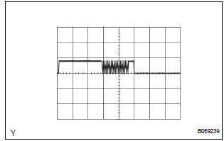
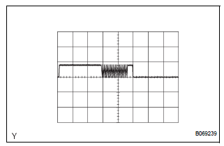
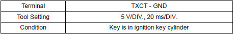
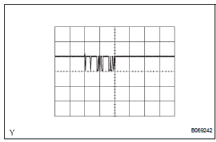
- Inspect using an oscilloscope.
- Wave form 1 (Reference):
- Wave form 2 (Reference):
- Wave form 3 (Reference):
- Wave form 4 (Reference):
3. CHECK ECM
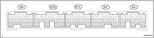
- Disconnect the E11 ECM connector and measure the resistance between the terminal of the wire harness side connector and body ground.

If the result is not as specified, there may be a malfunction on the wire harness side.
- Reconnect the E11 ECM. Measure the voltage between each terminal of the connector according to the value(s) in the table below.
If the result is not as specified, there may be a malfunction on the wire harness side.
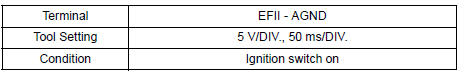
- Inspect using an oscilloscope.
- Waveform 1 (Reference):
- Waveform 2 (Reference):
 Problem symptoms table
ENGINE IMMOBILISER SYSTEM
...
 Diagnosis system
1. CHECK DLC3
The vehicle's ECU uses ISO 15765-4 for
communication protocol. The terminal arrangement
of the DLC3 complies with SAE J1962 and matches
the ISO 15765-4 format.
...
Other materials:
Mass air flow meter
COMPONENTS
ON-VEHICLE INSPECTION
1. INSPECT MASS AIR FLOW METER
NOTICE:
Perform the mass air flow (MAF) meter inspection
by following the procedures below.
Only replace the MAF meter when the MAF value
in the DATA LIST (with the engine stopped) are
not within th ...
Disassembly
1. REMOVE REAR DIFFERENTIAL CARRIER COVER
(a) Remove the 8 bolts from the carrier cover.
(b) Using a brass bar and a hammer, separate the
carrier cover from rear differential carrier assembly.
(c) Remove the breather plug from the rear differential
carrier cover.
(d) Remove the bol ...
Disassembly
1. REMOVE REAR NO. 2 SEAT COVER BEZEL
Remove the 3 screws.
Disengage the 3 claws and remove the rear No. 2
seat cover bezel.
2. REMOVE REAR SEAT RECLINING COVER RH
Remove the 2 screws.
Disengage the claw and remove the rear seat
reclining cover RH.
...
