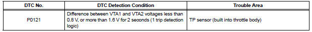
Toyota Sienna Service Manual: Throttle / Pedal Position Sensor / Switch "A" Circuit Range / Performance Problem

HINT: This DTC relates to the Throttle Position (TP) sensor.
DESCRIPTION
Refer to DTC P0120 (See page ES-145).
MONITOR DESCRIPTION
The ECM uses the TP sensor to monitor the throttle valve opening angle.
This sensor transmits two signals: VTA1 and VTA2. VTA1 is used to detect the throttle opening angle and VTA2 is used to detect malfunctions in VTA1. The ECM performs several checks to confirm the proper operation of the TP sensor and VTA1.
For each throttle opening angle, a specific voltage difference is expected between the outputs of VTA1 and VTA2. If the voltage output difference between the two signals deviates from the normal operating range, the ECM interprets this as a malfunction of the TP sensor. The ECM illuminates the MIL and sets the DTC.
If the malfunction is not repaired successfully, the DTC is set 2 seconds after the engine is next started.
MONITOR STRATEGY
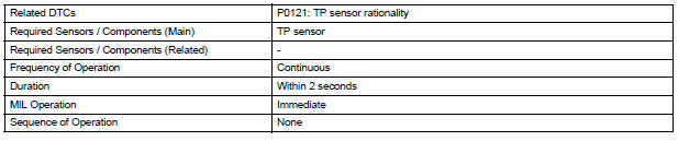
TYPICAL ENABLING CONDITIONS
TYPICAL MALFUNCTION THRESHOLDS

FAIL-SAFE
When this DTC, as well as other DTCs relating to ETCS (Electronic Throttle Control System) malfunctions, is set, the ECM enters fail-safe mode. During fail-safe mode, the ECM cuts the current to the throttle actuator off, and the throttle valve is returned to a 6.5° throttle angle by the return spring. The ECM then adjusts the engine output by controlling the fuel injection (intermittent fuel-cut) and ignition timing, in accordance with the accelerator pedal opening angle, to allow the vehicle to continue at a minimal speed. If the accelerator pedal is depressed slowly, the vehicle can be driven slowly.
Fail-safe mode continues until a pass condition is detected, and the ignition switch is then turned off.
INSPECTION PROCEDURE
HINT: Read freeze frame data using the intelligent tester. The ECM records vehicle and driving condition information as freeze frame data the moment a DTC is stored. When troubleshooting, freeze frame data can be helpful in determining whether the vehicle was running or stopped, whether the engine was warmed up or not, whether the air-fuel ratio was lean or rich, as well as other data recorded at the time of a malfunction.
1 CHECK ANY OTHER DTC OUTPUT (IN ADDITION TO DTC P0121)
(a) Connect the intelligent tester to the DLC3.
(b) Turn the ignition switch to the ON position.
(c) Turn the tester ON.
(d) Enter the following menus: DIAGNOSIS / ENHANCED OBD II / DTC INFO / CURRENT CODES.
(e) Read the DTC.
Result 
HINT: If any DTCs other than P0121 are output, troubleshoot those DTCs first.


REPLACE THROTTLE BODY
 Throttle / Pedal Position Sensor / Switch "A"
HINT:
These DTCs relate to the Throttle Position (TP) sensor.
DESCRIPTION
HINT:
This ETC (Electrical Throttle Control System) does not use a throttle cable.
The Throttle Position (TP) senso ...
 Insufficient Coolant Temperature for Closed Loop Fuel Control
DESCRIPTION
Refer to DTC P0115 (See page ES-133).
MONITOR DESCRIPTION
The resistance of the ECT sensor varies in proportion to the actual ECT. The
ECM supplies a constant
voltage to the ...
Other materials:
DVD Error/ Excess Current/ Tray Insertion / Ejection Error
DTC 44-44 DVD Error
DTC 44-48 Excess Current
DTC 44-50 Tray Insertion / Ejection Error
DESCRIPTION
DTC No.
DTC Detecting Condition
Trouble Area
44-44
Operation error in the DVD mechanism.
Television display assembly
44-48
Excess current is ...
Vehicle exterior
Items
Check points
Doors
Do the doors operate smoothly?
Engine hood
Does the engine hood lock system work
properly?
Fluid leaks
There should not be any signs of fluid
leakage after the vehicle ha ...
Disassembly
1. REMOVE RETURN TUBE NO.2
(a) Using SST, remove the return tube No. 2.
SST 09023-12701
2. REMOVE STEERING LEFT TURN PRESSURE TUBE
(a) Using SST, remove the left turn pressure tube.
SST 09023-38201
(b) Remove the 2 O-rings from the left turn pressure
tube.
3. REMOVE STEERING RIGH ...
