Toyota Sienna Service Manual: AVC-LAN Circuit
DESCRIPTION
Each unit of the audio system connected to the AVC-LAN (communication bus) transfers the signal of each switch by communication.
When a short to +B or short to ground occurs in this AVC-LAN, the audio system will not function normally as the communication is discontinued.
INSPECTION PROCEDURE
1 INSPECT RADIO RECEIVER
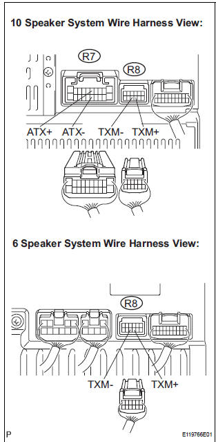
- Disconnect the radio receiver connectors.
- Measure the resistance according to the value(s) in the table below.
Standard resistance
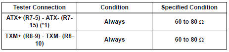
*1: 10 Speaker System
2 CHECK HARNESS AND CONNECTOR
HINT: For details of the connectors, refer to the "TERMINALS OF ECU"
- Referring to the AVC-LAN wiring diagram below, check all AVC-LAN circuits.
- Disconnect all connectors in all AVC-LAN circuits.
- Check for an open or short in all AVC-LAN circuits.
OK: There is no open or short circuit
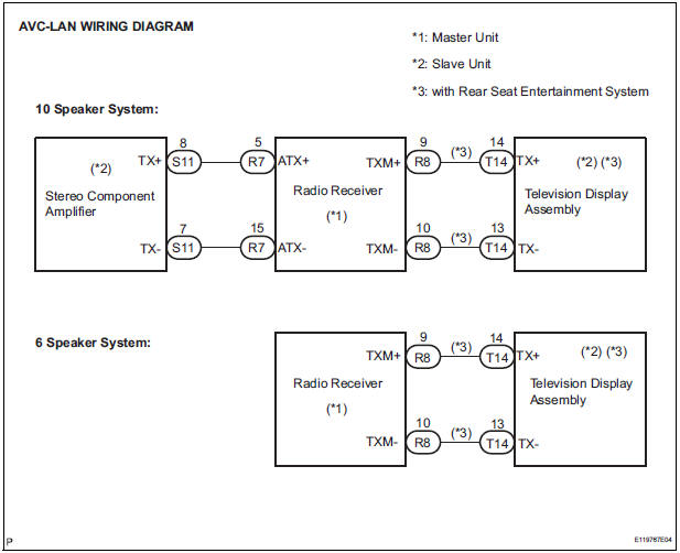
PROCEED TO NEXT CIRCUIT INSPECTION SHOWN IN PROBLEM SYMPTOMS TABLE
 Mute Signal Circuit between Radio Receiver and Television Display
Assembly
Mute Signal Circuit between Radio Receiver and Television Display
Assembly
DESCRIPTION
The radio receiver controls the volume according to the MUTE signal from the
television display
assembly.
The MUTE signal is sent to reduce noise and a popping sound generated when ...
 Vehicle Speed Signal Circuit between Multi-display and Combination
Meter
Vehicle Speed Signal Circuit between Multi-display and Combination
Meter
DESCRIPTION
This circuit is necessary for the ASL (Auto Sound Leveliser) built into the
radio receiver.
Speed signals are received from the combination meter and used for the ASL.
The ASL fun ...
Other materials:
On-vehicle inspection
1. INSPECT BRAKE PEDAL HEIGHT
(a) Check the brake pedal height.
Pedal height from dash panel:
150.3 to 160.3 mm (5.917 to 6.311 in.)
NOTICE:
Do not adjust the pedal height. Doing so by
changing the push rod length will structurally
change the pedal ratio.
2. CHECK AND ADJUST STOP LIGHT S ...
Driver Side Seat Belt Warning Light does not Operate
DESCRIPTION
When turning the ignition switch to the ON position, the combination meter
assembly communicates with
the supplemental restraint system by the multiplex communication system. Unless
the driver side seat
belt is fastened, the combination meter assembly will turn on the seat belt
...
Diagnosis system
1. DESCRIPTION
Front power seat control system data can be read
through the Data Link Connector 3 (DLC3) of the
vehicle. When the system seems to be
malfunctioning, use the intelligent tester to check for
malfunctions and perform repairs.
2. CHECK DLC3
The vehicle us ...
