Toyota Sienna Service Manual: VSC Warning Light Remains ON
DESCRIPTION
The skid control ECU is connected to the combination meter via CAN and multiplex communications.
If the skid control ECU stores DTCs to shut down TRAC and VSC operation, the VSC warning light comes on in the combination meter.
WIRING DIAGRAM
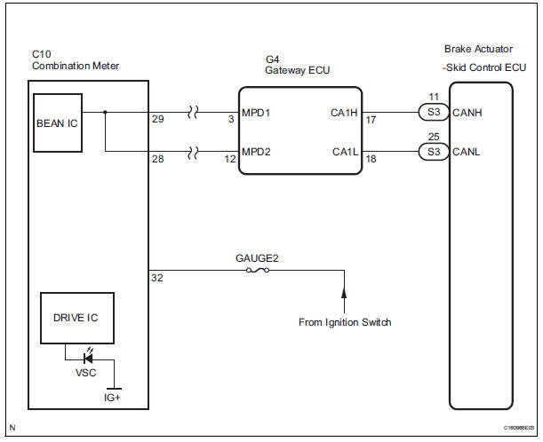
INSPECTION PROCEDURE
NOTICE: When replacing the brake actuator assembly, perform zero point calibration (See page BC-70).
1 CHECK CAN COMMUNICATION SYSTEM
(a) Check if the CAN communication system DTC is output (See page CA-17).
Result 

2 CHECK MULTIPLEX COMMUNICATION SYSTEM
(a) Check if the multiplex communication system DTC is output (See page MP-14).
Result 

3 CHECK IF SKID CONTROL ECU CONNECTOR IS SECURELY CONNECTED
(a) Check if the skid control ECU connector is securely connected.
OK: The connector is securely connected.

4 CHECK BATTERY
(a) Check the battery voltage.
Standard voltage: 11 to 14 V

5 INSPECT COMBINATION METER ASSEMBLY
(a) Check the combination meter (See page ME-4).
OK: The combination meter is normal.
HINT: If troubleshooting has been carried out according to the Problem Symptoms Table, refer back to the table and proceed to the next step before replacing the part (See page BC-79).

REPLACE BRAKE ACTUATOR ASSEMBLY
 ABS Warning Light does not Come ON
WIRING DIAGRAM
Refer to ABS Warning Light Remains ON (See page BC-141).
INSPECTION PROCEDURE
1 CHECK ABS WARNING LIGHT
(a) Disconnect the skid control ECU connector.
(b) Turn the ignition switc ...
 VSC Warning Light does not Come ON
DESCRIPTION
The skid control ECU is connected to the combination meter via CAN and
multiplex communications.
If the skid control ECU stores DTCs to shut down TRAC and VSC operation, the VSC
wa ...
Other materials:
Installation
1. INSTALL ACCELERATOR PEDAL ROD
NOTICE:
Avoid physical shock to the accelerator pedal
assembly.
Do not disassemble the accelerator pedal
assembly.
Install the accelerator pedal rod with the 2 nuts.
Torque: 4.9 N*m (50 kgf*cm, 43 in.*lbf)
Connect the ...
If your vehicle overheats
The following may indicate that your vehicle is overheating.
The needle of the engine coolant temperature gauge
enters the red zone or a loss of engine power is experienced. (For
example, the vehicle speed does not increase.)
The warning message indicating overheats is shown on the
mult ...
Mass air flow meter
COMPONENTS
ON-VEHICLE INSPECTION
1. INSPECT MASS AIR FLOW METER
NOTICE:
Perform the mass air flow (MAF) meter inspection
by following the procedures below.
Only replace the MAF meter when the MAF value
in the DATA LIST (with the engine stopped) are
not within th ...
