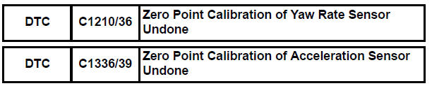
Toyota Sienna Service Manual: Zero Point Calibration of Yaw Rate Sensor Undone
DESCRIPTION
The skid control ECU receives signals from the yaw rate sensor via CAN communication system.
Yaw rate sensor has the built-in deceleration sensor.
If there is trouble in the bus lines between the yaw rate and deceleration sensor and CAN communication system, the DTC U0123/62 (yaw rate sensor communication trouble) and U0124/95 (deceleration sensor communication trouble) are output.
The DTC is also output when the calibration has not been completed.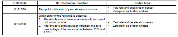
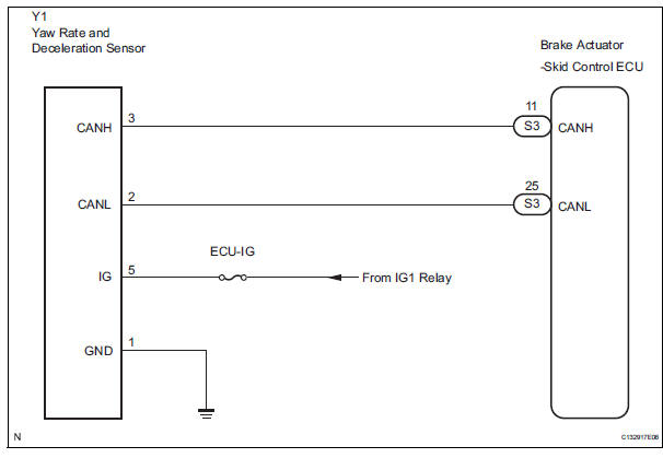
WIRING DIAGRAM
INSPECTION PROCEDURE
HINT: When U0073/94, U0100/65, U0123/62, U0124/95 or U0126/63 are output accompanied with C1210/36 or C1336/39, inspect and repair the trouble areas indicated by U0073/94, U0100/65, U0123/62, U0124/95 or U0126/63 first.
1 PERFORM ZERO POINT CALIBRATION OF YAW RATE AND DECELERATION SENSOR
(a) Perform the zero point calibration of the yaw rate and deceleration sensor (See page BC-70).

2 RECONFIRM DTC
(a) Clear the DTCs (See page BC-82).
(b) Turn the ignition switch to the ON position.
(c) Are the same DTCs recorded (See page BC-82).
Result

3 CHECK YAW RATE AND DECELERATION SENSOR INSTALLATION
(a) Check that the yaw rate and deceleration sensor has been installed properly (See page BC-197).
NOTICE: When replacing the yaw rate and deceleration sensor, perform zero point calibration (See page BC- 70).

REPLACE YAW RATE AND DECELERATION SENSOR
 ECM Communication Circuit Malfunction
DTC C1203/53 ECM Communication Circuit Malfunction
DESCRIPTION
The circuit is used to send TRAC and VSC control information from the skid
control ECU to the ECM, and
engine control information fr ...
 SM Solenoid Circuit
DTC C1225/25 SM Solenoid Circuit
DESCRIPTION
This solenoid turns on when receiving signals the ECU and controls the
pressure acting on the wheel
cylinders to control the braking force.
WIRIN ...
Other materials:
Inspection
1. INSPECT FRONT DIFFERENTIAL
(a) Using a dial indicator, measure the backlash of one
pinion gear while holding the front differential side
gear toward the case.
Standard backlash:
0.05 - 0.20 mm (0.0020 - 0.0079 in.)
NOTICE:
Do not mount the surface of front differential
case which cont ...
Transmission Fluid Temperature Sensor "A"
DESCRIPTION
The ATF (Automatic Transmission Fluid) temperature sensor converts the fluid
temperature into a
resistance value which is input into the ECM.
The ECM applies a voltage to the temperature sensor through ECM terminal THO1.
The sensor resistance changes with the transmission f ...
Open in Side Squib LH Circuit
DTC B0116/48 Open in Side Squib LH Circuit
DESCRIPTION
The side squib LH circuit consists of the center airbag sensor assembly and
the front seat side assembly
LH.
This circuit instructs the SRS to deploy when deployment conditions are met.
DTC B0116/48 is recorded when an open circuit is ...
