Toyota Sienna Service Manual: Transmission Range Sensor Circuit Malfunction (PRNDL Input)
DESCRIPTION
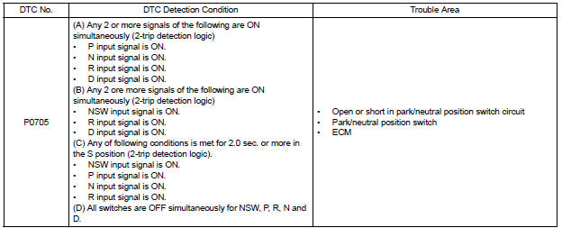
The park/neutral position switch detects the shift lever position and sends signals to the ECM.
HINT:
After confirming DTC P0705, use the intelligent tester to confirm the PNP switch signal in the ALL menu (to reach the ALL menu: DIAGNOSIS / ENHANCED OBD II / DATA LIST / ALL).
WIRING DIAGRAM
Refer to DTC P0705 for 2WD model (See page AX-40) or 4WD model (See page AX-40).
INSPECTION PROCEDURE
Refer to DTC P0705 for 2WD model (See page AX-41) or 4WD model (See page AX-41).
HINT:
Read freeze frame data using the intelligent tester or OBD II scan tool. The ECM records vehicle and driving condition information as freeze frame data the moment a DTC is stored. When troubleshooting, freeze frame data can help determine if the vehicle was running or stopped, if the engine was warmed up or not, if the air-fuel ratio was LEAN or RICH, and other data from the time the malfunction occurred.
 Actuator Supply Voltage Circuit / Open
DESCRIPTION
The ECM monitors the output voltage to the throttle actuator. This self-check
ensures that the ECM is
functioning properly. The output voltage is usually 0 V when the ignition swit ...
 Throttle Actuator Control Motor Circuit
DESCRIPTION
The throttle actuator is operated by the ECM and opens and closes the
throttle valve using gears.
The opening angle of the throttle valve is detected by the Throttle Position
( ...
Other materials:
On-vehicle inspection
1. CHECK RADIATOR RESERVOIR CAP SUBASSEMBLY
a) Measure the valve opening pressure.
(1) If there are water stains or foreign matter on
rubber packings 1, 2 or 3, clean the part(s) with
water and finger scouring.
(2) Check that rubber packings 1, 2 and 3 are not
deformed, cracked or swol ...
Reassembly
NOTICE:
Before installation, coat the parts indicated by arrows
with power steering fluid (See page PS-7).
1. INSTALL VANE PUMP HOUSING OIL SEAL
(a) Coat a new vane pump housing oil seal lip with
power steering fluid.
(b) Using SST and a press, install the vane pump
housing oil seal until i ...
Oxygen Sensor Circuit
HINT:
Sensor 2 refers to the sensor mounted behind the Three-Way Catalytic
Converter (TWC) and located far
from the engine assembly.
DESCRIPTION
A three-way catalytic converter (TWC) is used in order to convert the carbon
monoxide (CO), hydro
carbon (HC), and nitrogen oxides (HOx) into ...
