Toyota Sienna Service Manual: TC and CG Terminal Circuit
DESCRIPTION
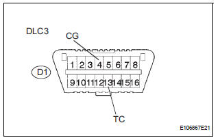
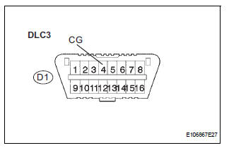
DTC output mode is set by connecting terminals TC and CG of the DLC3.
The DTCs are displayed by the blinking pattern of the ABS warning light.
WIRING DIAGRAM

HINT: When warning lights continue to blink, a ground short in the wiring of terminal TC of the DLC3 or an internal ground short in one or more ECU is suspected.
INSPECTION PROCEDURE
1 INSPECT DLC3 (BETWEEN TC of DLC3 AND CG of DLC3)
(a) Turn the ignition switch to the ON position.
(b) Measure the voltage according to the value(s) in the table below.
Standard voltage

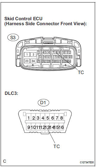
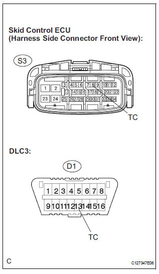
2 CHECK HARNESS AND CONNECTOR (BETWEEN SKID CONTROL ECU AND TC of DLC3)
(a) Turn the ignition switch off.
(b) Disconnect the skid control ECU connector.
(c) Measure the resistance according to the value(s) in the table below.
Standard resistance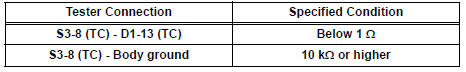
REPLACE BRAKE ACTUATOR ASSEMBLY
3 CHECK HARNESS AND CONNECTOR (BETWEEN CG of DLC3 AND BODY GROUND)
(a) Turn the ignition switch off.
(b) Measure the resistance according to the value(s) in the table below.
Standard resistance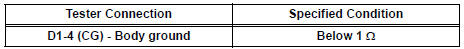

4 CHECK HARNESS AND CONNECTOR (BETWEEN SKID CONTROL ECU AND TC of DLC3)
(a) Disconnect the skid control ECU connector.
(b) Measure the resistance according to the value(s) in the table below.
Standard resistance 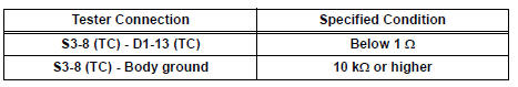

REPLACE BRAKE ACTUATOR ASSEMBLY
 Brake Warning Light does not Come ON
WIRING DIAGRAM
See page BC-52.
INSPECTION PROCEDURE
1 INSPECT BRAKE WARNING LIGHT
(a) Disconnect the skid control ECU connector.
(b) Turn the ignition switch to the on position.
(c) Check th ...
 TS and CG Terminal Circuit
DESCRIPTION
The Test Mode (signal check) circuit detects trouble in the sensor or switch
signal, which cannot be
detected by the DTC check.
Connecting terminals TS and CG of the DLC3 starts the ...
Other materials:
Disassembly
HINT:
On the RH side, use the same procedures as on the LH side.
1. REMOVE REAR DOOR WINDOW FRAME MOULDING
REAR LH (See page ET-30)
2. REMOVE REAR DOOR WINDOW FRAME MOULDING
SUB-ASSEMBLY LH (See page ET-21)
3. REMOVE SLIDE DOOR WINDOW GARNISH LH
Fully open the slide door window.
Remo ...
Preparation 2gr-fe cooling
SST
RECOMMENDED TOOLS
EQUIPMENT
COOLANT
Capacity
Classification
11.3 liters (12.0 US qts, 10.0 Imp. qts)
Use only "TOYOTA Super Long Life Coolant" or similar high quality
ethylene glycol based non-silicate, non-amine, non-nitrite, non-borate
coolant ...
Insufficient Coolant Temperature for Closed
Loop Fuel Control
DTC P0125 Insufficient Coolant Temperature for Closed
Loop Fuel Control
DESCRIPTION
Refer to DTC P0115
DTC No.
DTC Detection Condition
Trouble Area
P0125
Engine coolant temperature (ECT) does not reach
closed-loop enabling temperature for 20 minutes (t ...
