Toyota Sienna Service Manual: Vvt sensor
COMPONENTS
ON-VEHICLE INSPECTION
1. CHECK VVT SENSOR OUTPUT VOLTAGE
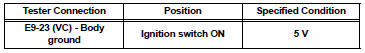
(a) Turn the ignition switch to the ON position.
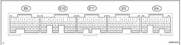
(b) Check the voltage between the specified terminal and body ground.
Standard voltage
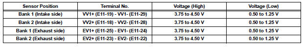
(c) While turning the crankshaft pulley by hand, measure the voltage between each terminal. Check that the voltage changes between the High range and Low range shown in the table below.
Standard voltage
REMOVAL
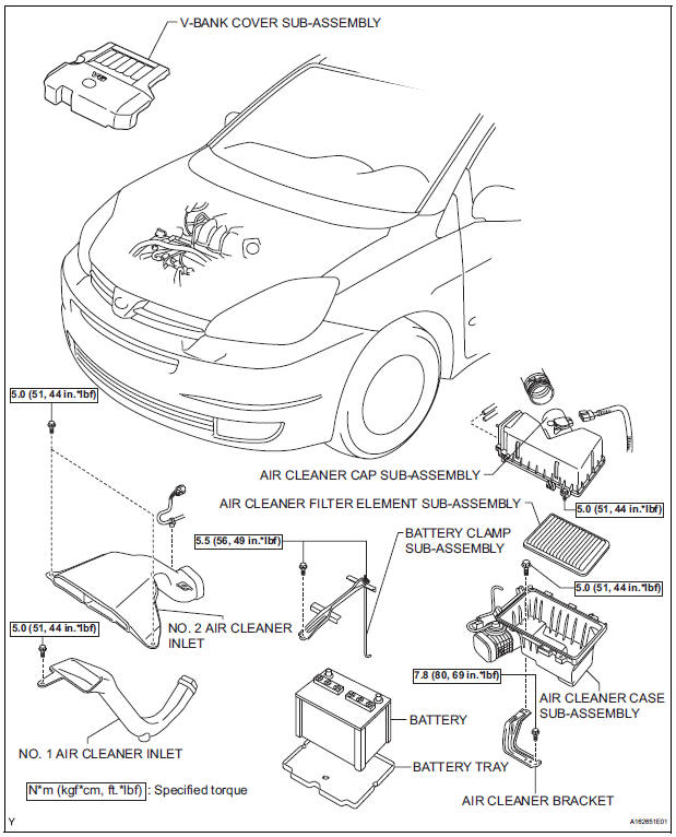
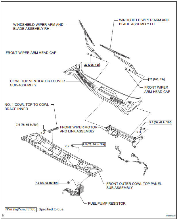
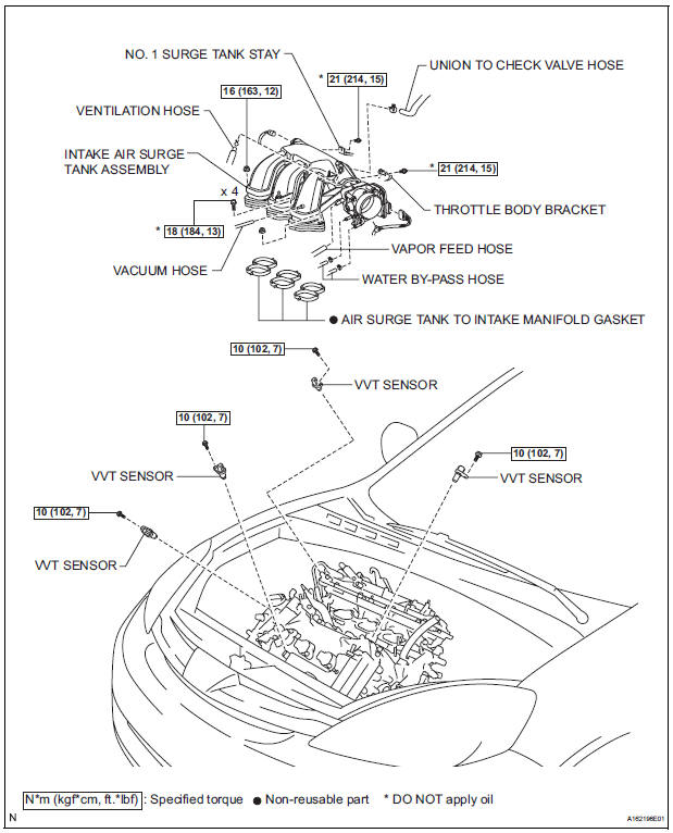
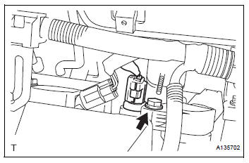
1. REMOVE WINDSHIELD WIPER MOTOR ASSEMBLY HINT: (See page WW-4) 2. REMOVE FRONT OUTER COWL TOP PANEL SUBASSEMBLY (See page EM-27) 3. DRAIN ENGINE COOLANT (See page CO-6) 4. REMOVE V-BANK COVER SUB-ASSEMBLY (See page EM-28) 5. REMOVE NO. 2 AIR CLEANER INLET (See page EM- 28) 6. REMOVE NO. 1 AIR CLEANER INLET (See page EM- 28) 7. REMOVE AIR CLEANER CAP SUB-ASSEMBLY (See page ES-493) 8. REMOVE AIR CLEANER CASE SUB-ASSEMBLY (See page EM-28) 9. REMOVE INTAKE AIR SURGE TANK ASSEMBLY (See page ES-521) 10. REMOVE VVT SENSOR (for Bank 1 Intake Side)
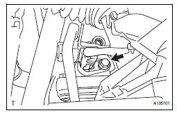
(a) Disconnect the VVT sensor connector.
(b) Remove the bolt and VVT sensor.
11. REMOVE VVT SENSOR (for Bank 1 Exhaust Side)
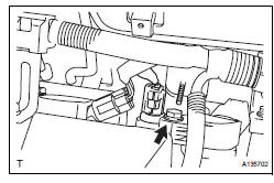
(a) Disconnect the VVT sensor connector.
(b) Remove the bolt and VVT sensor.
12. REMOVE VVT SENSOR (for Bank 2 Intake Side)
(a) Disconnect the VVT sensor connector.
(b) Remove the bolt and VVT sensor.
13. REMOVE VVT SENSOR (for Bank 2 Exhaust Side)
(a) Disconnect the VVT sensor connector.
(b) Remove the bolt and VVT sensor.
INSTALLATION
1. INSTALL VVT SENSOR (for Bank 2 Exhaust Side)
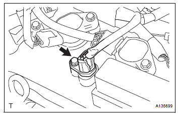
(a) Install the VVT sensor with the bolt.
Torque: 10 N*m (102 kgf*cm, 7 ft.*lbf) (b) Connect the VVT sensor connector.
2. INSTALL VVT SENSOR (for Bank 2 Intake Side)
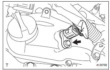
(a) Install the VVT sensor with the bolt.
Torque: 10 N*m (102 kgf*cm, 7 ft.*lbf) (b) Connect the VVT sensor connector.
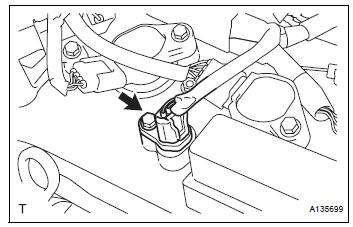
3. INSTALL VVT SENSOR (for Bank 1 Exhaust Side)
(a) Install the VVT sensor with the bolt.
Torque: 10 N*m (102 kgf*cm, 7 ft.*lbf) (b) Connect the VVT sensor connector.
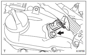
4. INSTALL VVT SENSOR (for Bank 1 Intake Side)
(a) Install the VVT sensor with the bolt.
Torque: 10 N*m (102 kgf*cm, 7 ft.*lbf) (b) Connect the VVT sensor connector.
5. INSTALL INTAKE AIR SURGE TANK ASSEMBLY (See page ES-522) 6. INSTALL AIR CLEANER CASE SUB-ASSEMBLY (See page EM-59) 7. INSTALL AIR CLEANER CAP SUB-ASSEMBLY (See page ES-496) 8. INSTALL NO. 1 AIR CLEANER INLET (See page EM- 59) 9. INSTALL NO. 2 AIR CLEANER INLET (See page EM- 60) 10. ADD ENGINE COOLANT (See page CO-7) 11. INSPECT FOR ENGINE COOLANT LEAK (See page CO-1) 12. INSPECT FOR ENGINE OIL LEAK (See page LU-6) 13. INSTALL V-BANK COVER SUB-ASSEMBLY (See page EM-63) 14. INSTALL FRONT OUTER COWL TOP PANEL SUBASSEMBLY (See page EM-61) 15. INSTALL WINDSHIELD WIPER MOTOR ASSEMBLY
HINT:
(See page WW-5)
 Mass air flow meter
COMPONENTS
ON-VEHICLE INSPECTION
1. INSPECT MASS AIR FLOW METER
NOTICE:
Perform the mass air flow (MAF) meter inspection
by following the procedures below.
Only replace t ...
 Crankshaft position sensor
Components
Removal
1. Remove compressor and magnetic clutch
HINT:
(See page AC-227 )
2. REMOVE CRANKSHAFT POSITION SENSOR
(a) Disconnect the crankshaft position sensor
connector.
(b) R ...
Other materials:
Oxygen (A/F) Sensor Pumping Current Circuit
DTC P2238 Oxygen (A/F) Sensor Pumping Current Circuit
Low (Bank 1 Sensor 1)
DTC P2239 Oxygen (A/F) Sensor Pumping Current Circuit
High (Bank 1 Sensor 1)
DTC P2241 Oxygen (A/F) Sensor Pumping Current Circuit
Low (Bank 2 Sensor 1)
DTC P2242 Oxygen (A/F) Sensor Pumping Current Circuit
High (Bank ...
How to proceed with
troubleshooting
HINT:
Troubleshoot in accordance with the procedures on the
following pages
1 VEHICLE BROUGHT TO WORKSHOP
2 CUSTOMER PROBLEM ANALYSIS CHECK AND SYMPTOM CHECK
3 INSPECT COMMUNICATION FUNCTION OF LARGE-SCALE MULTIPLEX
COMMUNICATION SYSTEM (BEAN)
Use the intelligent tester to check for normal ...
Removal
HINT:
Remove the RH side by the same procedure as the LH side.
1. REMOVE FRONT WHEEL
2. DRAIN BRAKE FLUID
NOTICE:
Wash the brake fluid off immediately if it attaches to
any painted surface.
3. REMOVE FRONT DISC BRAKE CYLINDER SUBASSEMBLY
(a) Remove the union bolt and 2 gaskets from the f ...
