Toyota Sienna Service Manual: ECM
COMPONENTS
REMOVAL
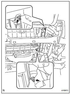
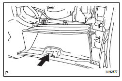
1. REMOVE GLOVE COMPARTMENT DOOR ASSEMBLY
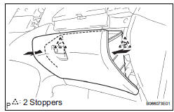
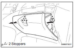
(a) Push the right side wall and then push the left wall to release the stoppers.
(b) Pull the glove compartment door sub-assembly rearward to remove it.
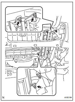
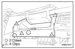
2. REMOVE NO. 2 INSTRUMENT PANEL BOX
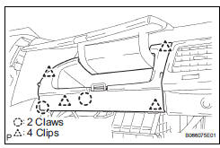
(a) Disengage the 2 claws and 4 clips, and remove the No. 2 instrument panel box.
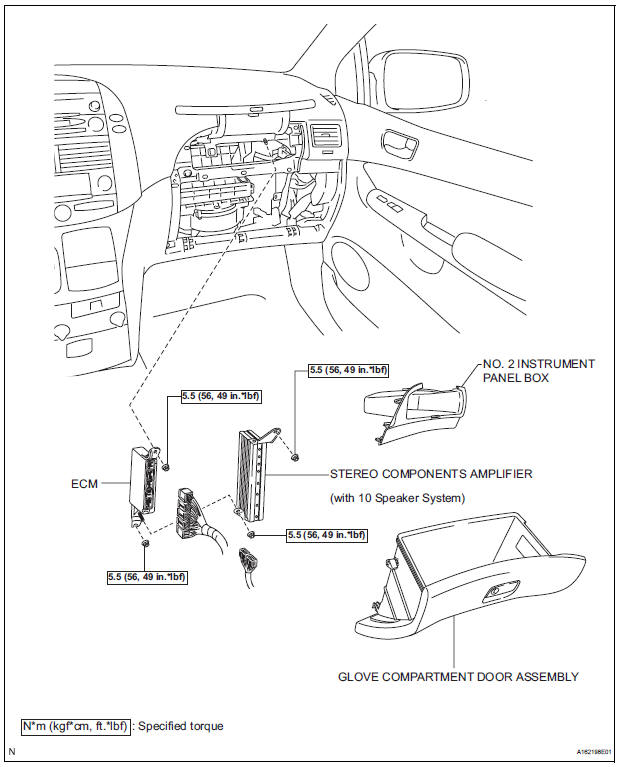
3. REMOVE ECM
(a) Disconnect the 5 ECM connectors.
(b) Remove the 2 nuts and ECM.
4. REMOVE ECM (with 10 speakers system)
(a) Disconnect the 5 ECM connectors and 2 stereo components amplifier connectors.
(b) Remove the 4 nuts and the ECM with the stereo components amplifier.
INSTALLATION
1. INSTALL ECM
(a) Install the ECM with the 2 nuts.
Torque: 5.5 N*m (56 kgf*cm, 49 in.*lbf) (b) Connect the 5 ECM connectors.
2. INSTALL ECM (with 10 speakers system)
(a) Install the ECM and stereo components amplifier with the 4 nuts.
Torque: 5.5 N*m (56 kgf*cm, 49 in.*lbf) (b) Connect the 5 ECM connectors and 2 stereo components amplifier connectors.
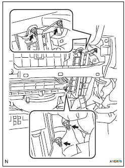
3.INSTALL NO. 2 INSTRUMENT PANEL BOX
(a) Install the No. 2 instrument panel box.
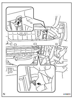
4. INSTALL GLOVE COMPARTMENT DOOR ASSEMBLY
(a) Install the glove compartment door sub-assembly frontward to install it.
(b) Push the right side wall and then push the left wall to install the stoppers.
5. PERFORM REGISTRATION
(a) When replacing the ECM, perform distance control ECU recognition in ECM (See page CC-125).
 Installation
1. INSTALL THROTTLE BODY
(a) Install a new throttle body gasket to the intake air
surge tank.
(b) Install the throttle body with the 4 bolts.
Torque: 10 N*m (102 kgf*cm, 7 ft.*lbf)
...
 Accelerator pedal rod
COMPONENTS
ON-VEHICLE INSPECTION
1. CHECK ACCELERATOR PEDAL ROD
(a) Check the voltage.
(1) Connect the intelligent tester to the DLC3.
(2) Turn the ignition switch to the ON position.
...
Other materials:
Power Slide Door Warning Buzzer RH does not Sound
DESCRIPTION
The power slide door system uses warning buzzers built into RH
slide doors respectively. Each buzzer
has 2 ways of sounding that are used differently according to the
situations:
When all the following conditions are met, the warning buzzer sounds at
a cycle of ...
Disassembly
1. REMOVE REAR NO. 2 SEAT COVER BEZEL
Remove the 3 screws.
Disengage the 3 claws and remove the rear No. 2
seat cover bezel.
2. REMOVE REAR SEAT RECLINING COVER RH
Remove the 2 screws.
Disengage the claw and remove the rear seat
reclining cover RH.
...
Front passenger side power
window switch
Inspection
1. INSPECT POWER WINDOW REGULATOR SWITCH ASSEMBLY
Check the resistance between the switch terminals
when the switch is operated.
Standard
If the result is not as specified, replace the switch
assembly. ...
