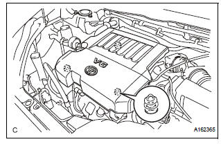
Toyota Sienna Service Manual: Engine assembly
Components
REMOVAL
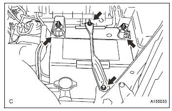
1. DISCHARGE FUEL SYSTEM PRESSURE (See page FU-13) 2. DISCHARGE REFRIGERANT FROM REFRIGERATION SYSTEM (See page AC-172) 3. REMOVE BATTERY
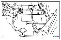
(a) Disconnect the negative battery terminal.
(b) Disconnect the positive battery terminal.
(c) Loosen the nut, and remove the bolt and battery clamp.
(d) Remove the battery and battery tray.
4. PLACE FRONT WHEELS FACING STRAIGHT AHEAD 5. REMOVE FRONT WHEELS
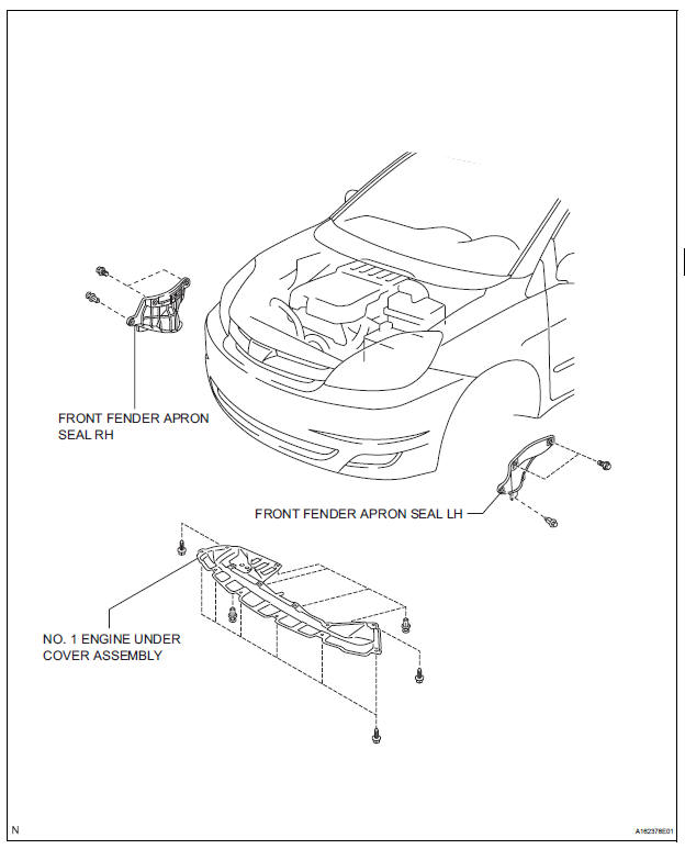
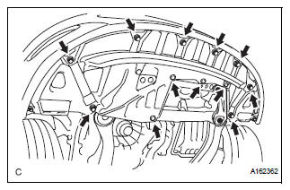
6. REMOVE NO. 1 ENGINE UNDER COVER ASSEMBLY
(a) Remove the 8 bolts, 4 clips and No. 1 engine under cover assembly.
7. REMOVE FRONT FENDER APRON SEAL RH

(a) Remove the 2 bolts, clip and front fender apron seal RH.
8. REMOVE FRONT FENDER APRON SEAL LH
(a) Remove the 2 bolts, clip and front fender apron seal LH.
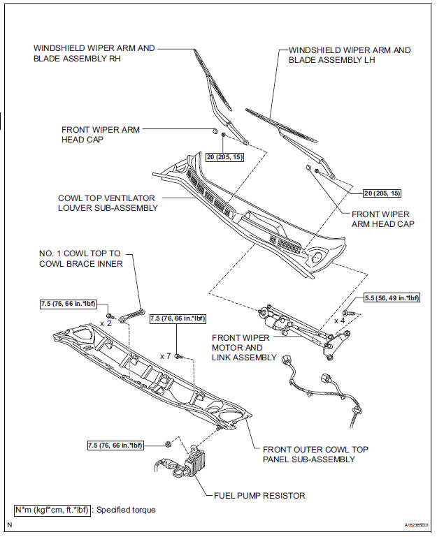
9. DRAIN ENGINE OIL (See page LU-4) 10. DRAIN ENGINE COOLANT (See page CO-6) 11. DRAIN AUTOMATIC TRANSAXLE FLUID (See page AX-159) 12. REMOVE FRONT WIPER ARM HEAD CAP (See page WW-4) 13. REMOVE WINDSHIELD WIPER ARM AND BLADE ASSEMBLY RH (See page WW-4)
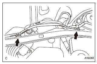
14. REMOVE WINDSHIELD WIPER ARM AND BLADE ASSEMBLY LH (See page WW-4) 15. REMOVE COWL TOP VENTILATOR LOUVER SUBASSEMBLY (See page WW-4) 16. REMOVE FRONT WIPER MOTOR AND LINK ASSEMBLY (See page WW-4) 17. REMOVE NO. 1 COWL TOP TO COWL BRACE INNER
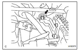
(a) Remove the 2 bolts, 2 clips and No. 1 cowl top to cowl brace inner.
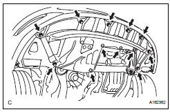
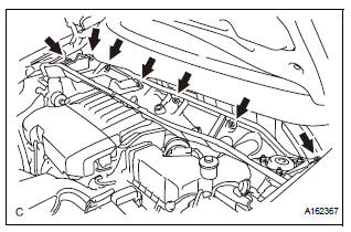
18. REMOVE FRONT OUTER COWL TOP PANEL SUBASSEMBLY
(a) Remove the nut, and separate the fuel pump resistor.
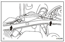
(b) Remove the 2 clips, and separate the engine wire.
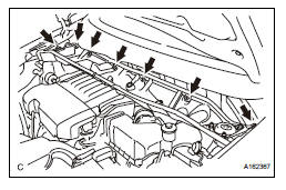
(c) Remove the 7 bolts and front outer cowl top panel sub-assembly.
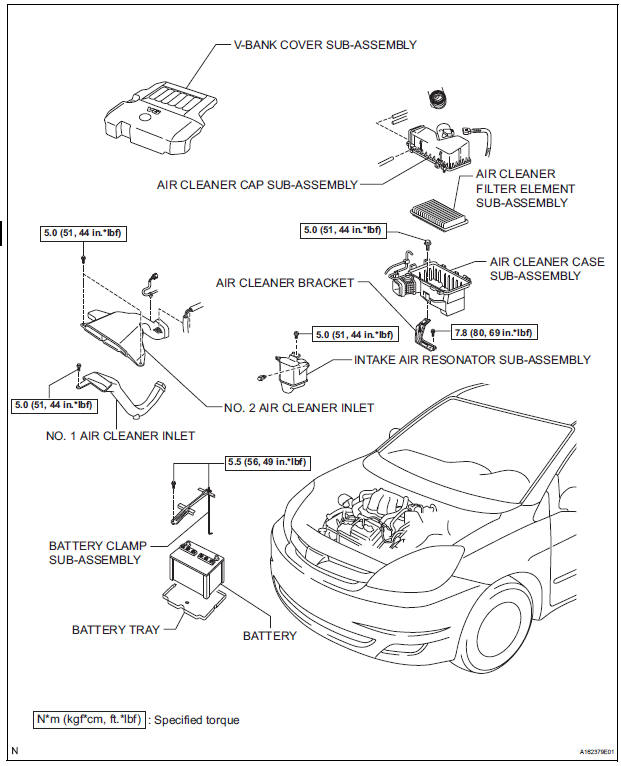
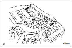
19. REMOVE V-BANK COVER SUB-ASSEMBLY
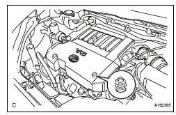
(a) Hold the front of the V-bank cover and raise it to disengage the 2 clips on the front of the cover.
Continue to raise the cover to disengage the clip on the rear of the cover and remove the cover.
| NOTICE: Attempting to disengage both front and rear clips at the same time may cause the cover to break. |
20. REMOVE NO. 2 AIR CLEANER INLET
(a) Disconnect the vacuum switching valve clamp.
(b) Disconnect the 2 vacuum hoses.
(c) Remove the 2 bolts and No. 2 air cleaner inlet.
21. REMOVE NO. 1 AIR CLEANER INLET
22. REMOVE AIR CLEANER CAP SUB-ASSEMBLY (See page IT-4) 23. REMOVE AIR CLEANER FILTER ELEMENT SUBASSEMBLY
(a) Remove the air cleaner filter element sub-assembly.
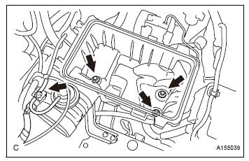
24. REMOVE AIR CLEANER CASE SUB-ASSEMBLY

(a) Disconnect the vacuum switching valve connector.
(b) Disconnect the vacuum hose.
(c) Remove the 3 bolts and air cleaner case.
25. REMOVE AIR CLEANER BRACKET
(a) Remove the 2 bolts and air cleaner bracket.
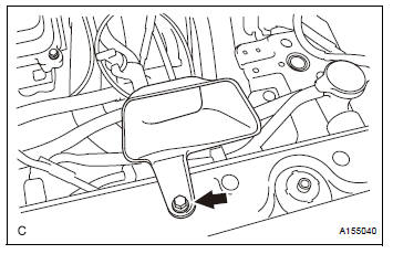
26. REMOVE INTAKE AIR RESONATOR SUB-ASSEMBLY
(a) Remove the clip, bolt and intake air resonator.
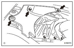
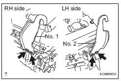
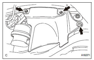
27. REMOVE NO. 2 ENGINE MOUNTING STAY RH
(a) Remove bolt, 2 nuts and No. 2 engine mounting stay RH.
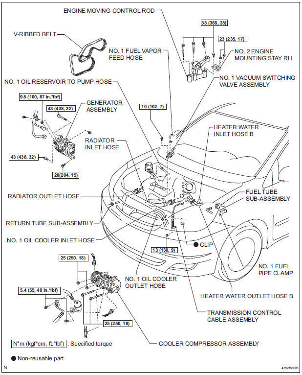
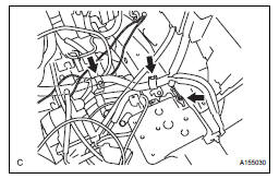
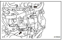
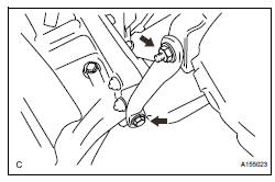
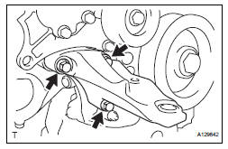
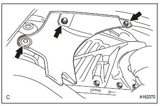
28. REMOVE ENGINE MOVING CONTROL ROD
(a) Remove the 3 bolts and engine moving control rod.
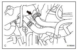
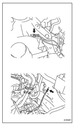
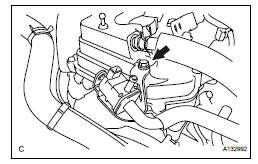
29. DISCONNECT NO. 1 FUEL VAPOR FEED HOSE
(a) Remove the clamp and disconnect the No. 1 fuel vapor feed hose.
30. DISCONNECT RADIATOR INLET HOSE
(a) Using pliers, grip the claws of the clip and slide the clip to disconnect radiator inlet hose from the water outlet.
31. DISCONNECT RADIATOR OUTLET HOSE
(a) Using pliers, grip the claws of the clip and slide the clip to disconnect the radiator outlet hose from the water inlet.
32. DISCONNECT HEATER WATER OUTLET HOSE B
(a) Using pliers, grip the claws of the clip and slide the clip to disconnect heater water inlet hose B from the water inlet.
33. DISCONNECT HEATER WATER INLET HOSE B
(a) Using pliers, grip the claws of the clip and slide the clip to disconnect heater water outlet hose B from the water outlet.
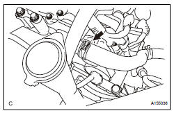
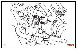
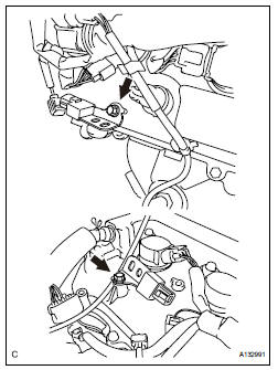
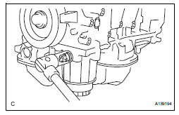
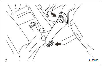
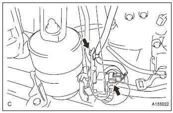
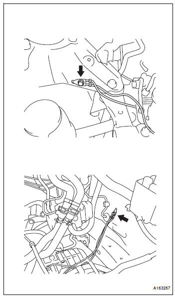
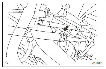
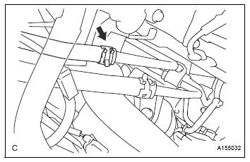
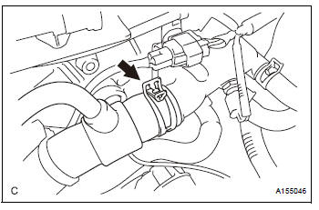
34. DISCONNECT FUEL TUBE SUB-ASSEMBLY
(a) Remove the No. 1 fuel pipe clamp.
(b) Disconnect the fuel tube from the fuel pipe while pinching part A with your fingers as shown in the illustration.
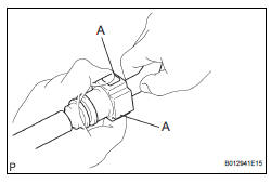
NOTICE:
|
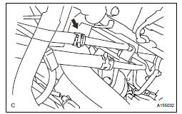
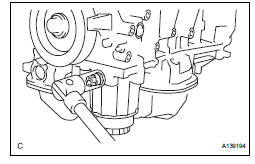
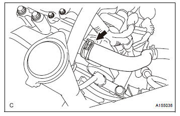
35. DISCONNECT NO. 1 OIL COOLER INLET HOSE
(a) Using pliers, grip the claws of the clip and slide the clip to disconnect the No. 1 oil cooler inlet hose from the No. 1 oil cooler inlet tube.
36. REMOVE NO. 1 OIL COOLER OUTLET HOSE
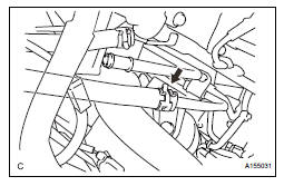
(a) Using pliers, grip the claws of the clip and slide the clip to disconnect the No. 1 oil cooler outlet hose from the No. 1 oil cooler outlet tube.
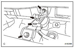
37. DISCONNECT TRANSMISSION CONTROL CABLE ASSEMBLY
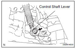
(a) Remove the nut from the control shaft lever.
(b) Disconnect the transmission control cable assembly from the control shaft lever.
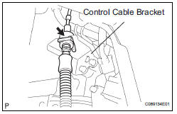
(c) Remove the clip and disconnect the transmission control cable assembly from the control cable bracket.
(d) Disconnect the control cable from the control cable clamp.
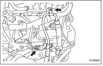
38. DISCONNECT RETURN TUBE SUB-ASSEMBLY
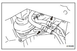
(a) Using pliers, grip the claws of the 2 clips and slide the 2 clips to disconnect the 2 return tube subassemblies.
(b) Drain the power steering fluid.
| NOTICE: Take care not to damage the hose protector. |
39. DISCONNECT NO. 1 OIL RESERVOIR TO PUMP HOSE
(a) Using pliers, grip the claws of the clip and slide the clip to disconnect the No. 1 oil reservoir to pump hose from the oil reservoir tank.
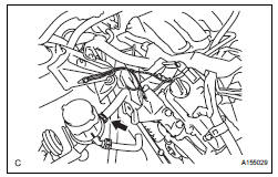
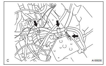
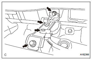
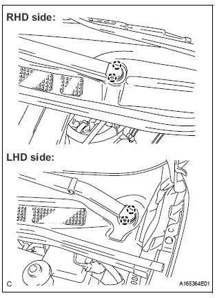
40. DISCONNECT ENGINE WIRE
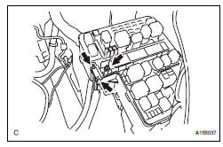
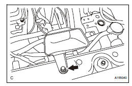
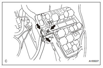
(a) Disconnect the engine wire from the engine room junction block.
(1) Remove the nut and separate the wire harness.
(2) Using a screwdriver, unlock the engine room junction block. Pull the engine room junction block upward.
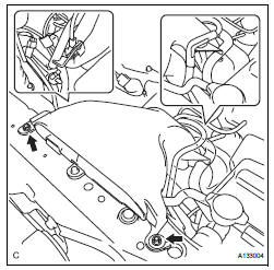
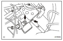
(b) Remove the bolt and 2 clamps from the body.
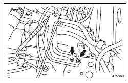
(c) Remove the 2 bolts and 2 ground cables.
(d) Disconnect the engine wire from the ECM and passenger side junction block.
41. DISCONNECT UNION TO CHECK VALVE HOSE
(a) Using pliers, grip the claws of the clip and slide the clip to disconnect the union to check valve hose.
42. REMOVE CENTER EXHAUST PIPE ASSEMBLY (for 4WD)
(a) Remove the center exhaust pipe assembly (See page EX-8).
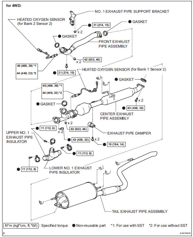
43. REMOVE FRONT EXHAUST PIPE ASSEMBLY (for 4WD)
(a) Remove the front exhaust pipe assembly (See page EX-9).
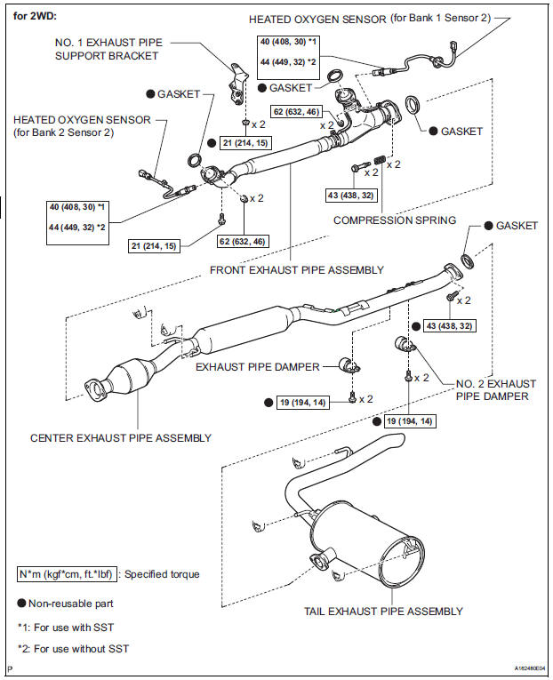
44. REMOVE FRONT EXHAUST PIPE ASSEMBLY (for 2WD)
(a) Remove the front exhaust pipe assembly (See page EX-3).
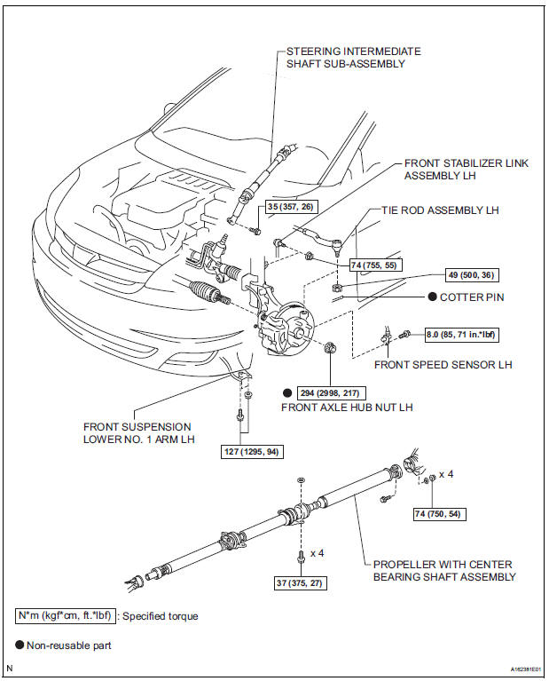
45. REMOVE PROPELLER WITH CENTER BEARING SHAFT ASSEMBLY (See page PR-3) 46. DISCONNECT FRONT STABILIZER LINK ASSEMBLY LH (See page DS-5) 47. DISCONNECT FRONT STABILIZER LINK ASSEMBLY RH
HINT: Use the same procedures described for the LH side.
48. REMOVE FRONT AXLE HUB NUT LH (See page DS- 5) 49. REMOVE FRONT AXLE HUB NUT RH
HINT: Use the same procedures described for the LH side.
50. DISCONNECT FRONT SPEED SENSOR LH (See page DS-5) 51. DISCONNECT FRONT SPEED SENSOR RH
HINT: Use the same procedures described for the LH side.
52. DISCONNECT TIE ROD ASSEMBLY LH (See page DS-6) 53. DISCONNECT TIE ROD ASSEMBLY RH
HINT: Use the same procedures described for the LH side.
54. SEPARATE FRONT SUSPENSION LOWER NO. 1 ARM LH (See page DS-6) 55. SEPARATE FRONT SUSPENSION LOWER NO. 1 ARM RH
HINT: Use the same procedures described for the LH side.
56. SEPARATE FRONT AXLE ASSEMBLY LH (See page DS-6) 57. SEPARATE FRONT AXLE ASSEMBLY RH
HINT: Use the same procedures described for the LH side.
58. DISCONNECT STEERING INTERMEDIATE SHAFT SUB-ASSEMBLY 59. DISCONNECT DISCHARGE HOSE SUB-ASSEMBLY (See page AC-227) 60. DISCONNECT SUCTION HOSE SUB-ASSEMBLY (See page AC-227) 61. REMOVE ENGINE ASSEMBLY WITH TRANSAXLE
(a) Set the engine lifter.
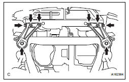
(b) Remove the 6 bolts, 2 nuts, and frame side rail plates RH and LH.
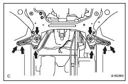
(c) Remove the 6 bolts, 2 nuts, and front suspension member brace rear RH and LH.
(d) Operate the engine lifter, then remove the engine assembly from the vehicle.
| NOTICE: Make sure that the engine is clear of all wiring and hoses. |
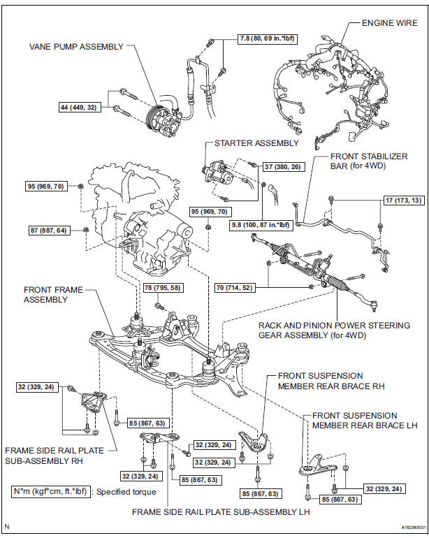
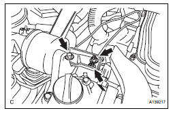
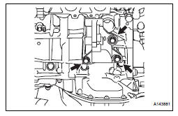
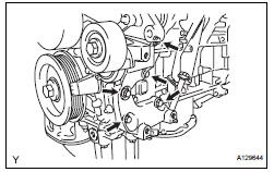
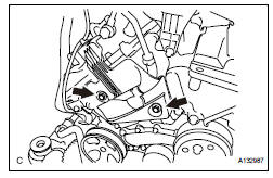
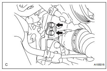
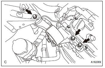
62. REMOVE V-RIBBED BELT (See page EM-6) 63. REMOVE VANE PUMP ASSEMBLY
(a) Disconnect the power steering oil pressure switch connector.
(b) Remove the 2 nuts.
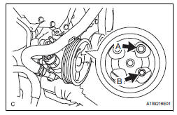
(c) Loosen the bolt A.
(d) Remove the bolt B.
(e) Remove the bolt A and vane pump assembly.
64. REMOVE FRONT STABILIZER BAR (for 4WD)
HINT: See page SP-35.
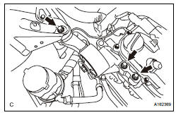
65. REMOVE POWER STEERING LINK
(a) Remove the 2 bolts and power steering link with vane pump.
66. INSTALL ENGINE HANGERS
(a) Install the 2 engine hangers with the 4 bolts as shown in the illustration.
Part No.: No. 1 Engine hanger 12281-31120 No. 2 Engine hanger 12282-31100 Bolts 91671-10825 Torque: 33 N*m (337 kgf*cm, 24 ft.*lbf)
(b) Attach the engine sling device and hang the engine with the chain block.
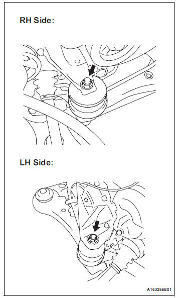
67. REMOVE FRONT FRAME ASSEMBLY
(a) Disconnect the active mount VSV connector and harness clamp.
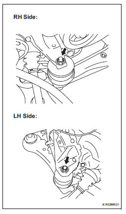
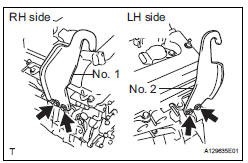
(b) Remove the 2 nuts and disconnect the engine mounting insulators RH and LH.
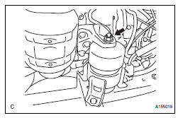
(c) Remove the bolt and disconnect the engine mounting insulator FR.
(d) Remove the 2 bolts and separate the engine mounting insulator RR (for 4WD).
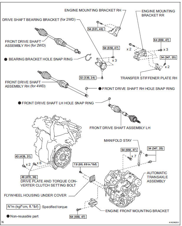
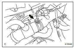
68. REMOVE FRONT DRIVE SHAFT ASSEMBLY LH (See page DS-6) 69. REMOVE FRONT DRIVE SHAFT ASSEMBLY RH (for 2WD) (See page DS-6) 70. REMOVE FRONT DRIVE SHAFT ASSEMBLY RH (for 4WD) (See page DS-7) 71. REMOVE ENGINE WIRE 72. REMOVE STARTER ASSEMBLY (See page ST-5) 73. REMOVE ENGINE FRONT MOUNTING BRACKET (See page AX-165) 74. REMOVE MANIFOLD STAY (a) Remove the bolt, nut, and manifold stay.
75. REMOVE TRANSFER STIFFENER PLATE RH (See page AX-166) 76. REMOVE AUTOMATIC TRANSAXLE ASSEMBLY (for 2WD)
HINT: See page AX-165.
77. REMOVE AUTOMATIC TRANSAXLE ASSEMBLY (for 4WD) AX-166 78. REMOVE DRIVE PLATE AND RING GEAR SUBASSEMBLY (See page EM-12) 79. SECURE ENGINE
(a) Secure the engine onto an engine stand with the bolts.
(b) Remove the engine hangers.
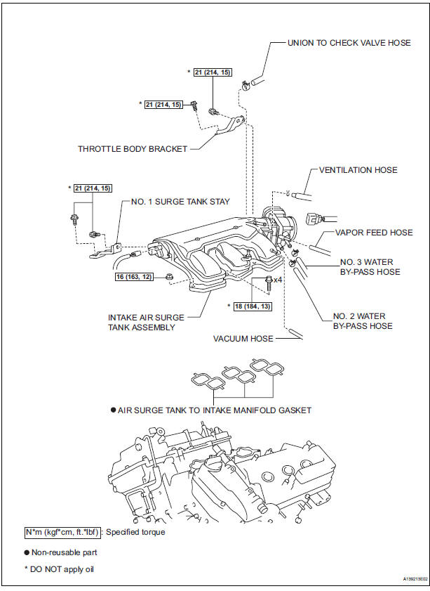
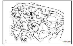
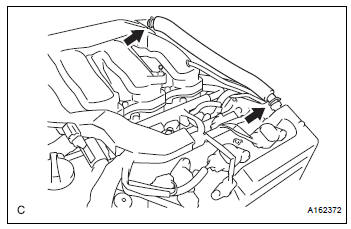
80. REMOVE VENTILATION HOSE
(a) Using pliers, grip the claws of the 2 clips and slide the 2 clips to remove the ventilation hose.
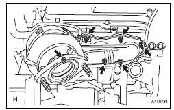
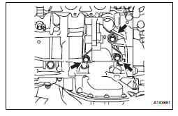
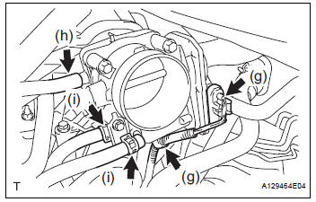
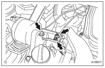
81. REMOVE INTAKE AIR SURGE TANK ASSEMBLY
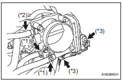
(a) Disconnect the 2 water by-pass hoses from the throttle with motor body assembly (*1).
(b) Disconnect the vapor feed hose (*2).
(c) Disconnect the throttle with motor body assembly connector and clamp (*3).
(d) Disconnect the No. 1 ventilation hose.
(e) Disconnect the connector.
(f) Remove the 4 bolts, No. 1 surge tank stay and throttle body bracket.
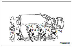
(g) Using a 5 mm socket hexagon wrench, remove the 4 bolts.
(h) Remove the 2 nuts and intake air surge tank (*4).
(i) Remove the gasket from the intake air surge tank (*5).
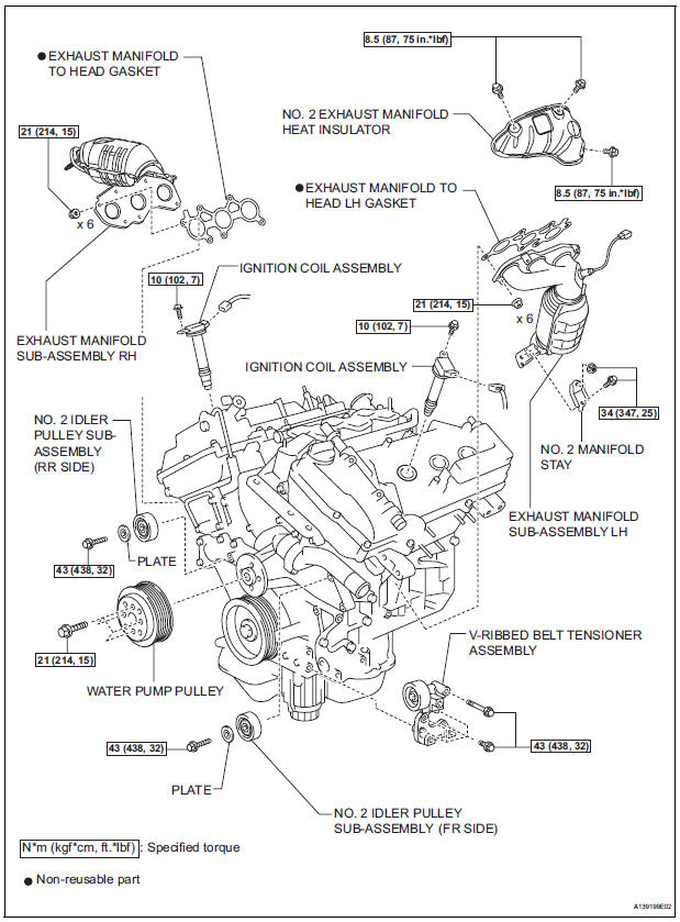
82. REMOVE IGNITION COIL ASSEMBLY
(a) Remove the 6 bolts and 6 ignition coils.
83. REMOVE NO. 2 ENGINE MOUNTING STAY RH
(a) Remove the bolt and No. 2 engine mounting stay RH.
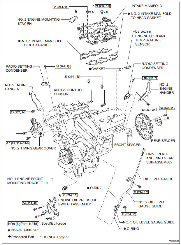
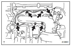
84. REMOVE INTAKE MANIFOLD
(a) Uniformly loosen and remove the 6 bolts and 4 nuts.
(b) Remove the intake manifold and 2 gaskets.
85. REMOVE EXHAUST MANIFOLD SUB-ASSEMBLY RH
(a) Disconnect the A/F sensor connector clamp.
(b) Uniformly loosen and remove the 6 nuts.
(c) Remove the manifold and gasket.
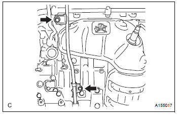
86. REMOVE OIL LEVEL GAUGE GUIDE SUBASSEMBLY
(a) Remove the oil level gauge.
(b) Remove the 2 bolts, No. 1 and No. 2 oil level gauge guides.
(c) Remove the O-rings from the oil level gauge guide.
87. REMOVE NO. 2 MANIFOLD STAY

(a) Remove the bolt, nut and No. 2 manifold stay.
88. REMOVE NO. 2 EXHAUST MANIFOLD HEAT INSULATOR
(a) Remove the 3 bolts and No. 2 insulator.
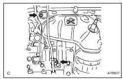
89. REMOVE EXHAUST MANIFOLD SUB-ASSEMBLY LH
(a) Uniformly loosen and remove the 6 nuts.
(b) Remove the manifold and gasket.
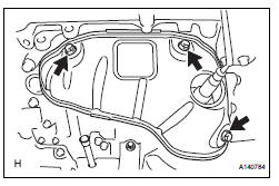
90. REMOVE ENGINE MOUNTING BRACKET RH
(a) Remove the engine mounting bracket and 3 bolts.
91. REMOVE DRIVE SHAFT BEARING BRACKET (for 2WD)
(a) Remove the 3 bolts and drive shaft bearing bracket.
92. REMOVE ENGINE MOUNTING BRACKET RR (for 4WD)
(a) Remove the 3 bolts and engine mounting bracket RR.
93. REMOVE GENERATOR ASSEMBLY (See page CH-17) 94. REMOVE COOLER COMPRESSOR ASSEMBLY
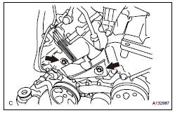
95. REMOVE V-RIBBED BELT TENSIONER ASSEMBLY
(a) Remove the 5 bolts and V-ribbed belt tensioner assembly.
96. REMOVE NO. 2 TIMING GEAR COVER
(a) Remove the 2 bolts and No. 2 timing gear cover.
97. REMOVE NO. 2 IDLER PULLEY SUB-ASSEMBLY
(a) Remove the bolt, plate and No. 2 idler pulley subassembly.
98. REMOVE WATER PUMP PULLEY (See page CO-12)
99. REMOVE NO. 1 ENGINE FRONT MOUNTING BRACKET LH
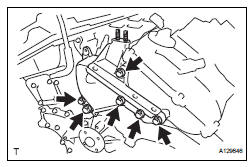
(a) Remove the 6 bolts and No. 1 engine front mounting bracket LH.
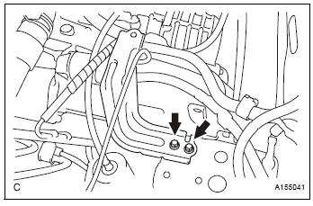
100.REMOVE RADIO SETTING CONDENSER
(a) Remove the 2 bolts and 2 radio setting condensers.
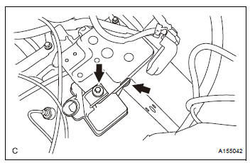
101.REMOVE NO. 1 VACUUM SWITCHING VALVE ASSEMBLY
(a) Remove the bolt and No. 1 vacuum switching valve.

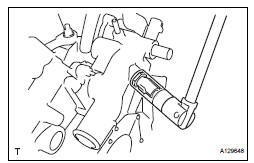
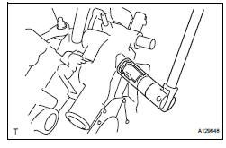
102.REMOVE ENGINE OIL PRESSURE SWITCH ASSEMBLY
(a) Using a 24 mm deep socket wrench, remove the engine oil pressure switch assembly.
103.REMOVE KNOCK CONTROL SENSOR (See page ES- 522)
104.REMOVE ENGINE COOLANT TEMPERATURE SENSOR
(a) Using a 19 mm deep socket wrench, remove the EFI engine coolant temperature sensor and gasket.
INSPECTION
1. INSPECT EXHAUST MANIFOLD SUB-ASSEMBLY LH
(a) Using a precision straightedge and feeler gauge, measure the warpage on the contact surface of the cylinder head.
Maximum warpage: 0.7 mm (0.028 in.)
HINT: The maximum allowable warpage of each installation surface is 0.3 mm (0.012 in.).
If the warpage is greater than the maximum, replace the manifold.
2. INSPECT EXHAUST MANIFOLD SUB-ASSEMBLY RH

(a) Using a precision straightedge and feeler gauge, measure the warpage on the contact surface of the cylinder head.
Maximum warpage: 0.7 mm (0.028 in.)
HINT: The maximum allowable warpage of each installation surface is 0.3 mm (0.012 in.).
If the warpage is greater than the maximum, replace the manifold.
3. INSPECT INTAKE AIR SURGE TANK ASSEMBLY
(a) Using a precision straightedge and feeler gauge, measure the warpage on the contact surface of the intake manifold.
Maximum warpage: 2.5 mm (0.098 in.) If the warpage is greater than the maximum, replace the surge tank.
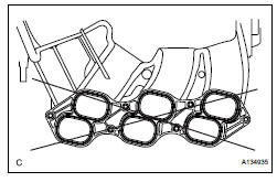
4. INSPECT INTAKE MANIFOLD
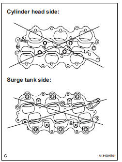
(a) Cylinder head side:
(1) Using a precision straightedge and feeler gauge, measure the surface contacting the cylinder head for warpage.
Maximum warpage: 0.1 mm (0.003 in.) If the warpage is greater than the maximum, replace the intake manifold.
(b) Surge tank side:
(1) Using a precision straightedge and feeler gauge, measure the surface contacting the surge tank for warpage.
Maximum warpage: 0.1 mm (0.003 in.) If the warpage is greater than the maximum, replace the intake manifold.
INSTALLATION
1. INSTALL ENGINE COOLANT TEMPERATURE SENSOR
(a) Using a 19 mm deep socket wrench, install the engine coolant temperature sensor and a new gasket.
Torque: 20 N*m (200 kgf*cm, 14 ft.*lbf)
2. INSTALL KNOCK CONTROL SENSOR (See page ES- 522) 3. INSTALL ENGINE OIL PRESSURE SWITCH ASSEMBLY
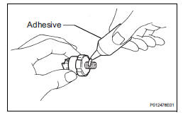
(a) Clean the threads of the oil pressure switch. Apply adhesive to 2 or 3 threads of the oil pressure switch.
Adhesive: Part No. 08833-00080, THREE BOND 1344, LOCTITE 242 or equivalent
(b) Using a 24 mm deep socket wrench, install the oil pressure switch.
Torque: 21 N*m (214 kgf*cm, 15 ft.*lbf)
| NOTICE: Do not start the engine within 1 hour after installation to prevent oil leaks. |
4. INSTALL NO. 1 VACUUM SWITCHING VALVE ASSEMBLY
(a) Install the bolt and No. 1 vacuum switching valve.
Torque: 10 N*m (102 kgf*cm, 7 ft.*lbf)
5. INSTALL RADIO SETTING CONDENSER

(a) Install the 2 bolts and 2 radio setting condensers.
Torque: 10 N*m (102 kgf*cm, 7 ft.*lbf)
6. INSTALL NO. 1 ENGINE FRONT MOUNTING BRACKET LH
(a) Install the No. 1 engine front mounting bracket LH with the 6 bolts.
Torque: 54 N*m (551 kgf*cm, 40 ft.*lbf)
7. INSTALL WATER PUMP PULLEY (See page CO-13)
8. INSTALL NO. 2 IDLER PULLEY SUB-ASSEMBLY
(a) Install the No. 2 idler pulley sub-assembly and cover plate with the bolt.
Torque: 43 N*m (438 kgf*cm, 32 ft.*lbf)
9. INSTALL NO. 2 TIMING GEAR COVER
(a) Install the No. 2 timing gear cover with the 2 bolts.
Torque: 6.0 N*m (61 kgf*cm, 53 in.*lbf)
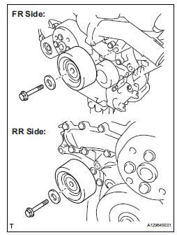
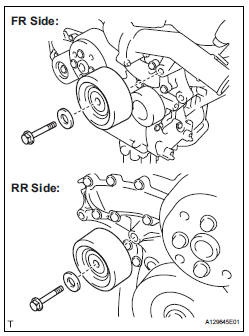
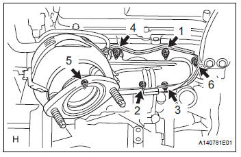
10. INSTALL V-RIBBED BELT TENSIONER ASSEMBLY

(a) Temporarily install the V-ribbed belt tensioner with the 5 bolts.
HINT: Each bolt length is as follows: A: 70 mm (2.76 in.) B: 33 mm (1.30 in.)
(b) Install the V-ribbed belt tensioner by tightening the bolt 1 and bolt 2 in the order shown in the illustration.
Torque: 43 N*m (438 kgf*cm, 32 ft.*lbf) (c) Tighten the other bolts.
Torque: 43 N*m (438 kgf*cm, 32 ft.*lbf)
11. INSTALL GENERATOR ASSEMBLY (See page CH-26) 12. INSTALL COOLER COMPRESSOR ASSEMBLY (See page AC-231)
13. INSTALL ENGINE MOUNTING BRACKET RR (for 4WD)
(a) Install the engine mounting bracket RR with the 3 bolts.
Torque: 64 N*m (650 kgf*cm, 47 ft.*lbf)
14. INSTALL DRIVE SHAFT BEARING BRACKET (for 2WD)
(a) Install the drive shaft bearing bracket with the 3 bolts.
Torque: 64 N*m (650 kgf*cm, 47 ft.*lbf)
15. INSTALL ENGINE MOUNTING BRACKET RH
(a) Install the engine mounting bracket RH with the 3 bolts.
Torque: 54 N*m (551 kgf*cm, 40 ft.*lbf)
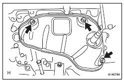
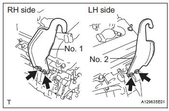
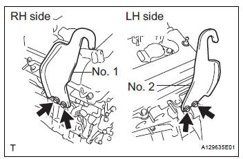
16. INSTALL EXHAUST MANIFOLD SUB-ASSEMBLY LH
(a) Install a new gasket as shown in the illustration.
(b) Install the exhaust manifold sub-assembly LH with the 6 nuts in the order shown in the illustration.
Torque: 21 N*m (214 kgf*cm, 15 ft.*lbf)
17. INSTALL NO. 2 EXHAUST MANIFOLD HEAT INSULATOR
(a) Install the No. 2 insulator with the 3 bolts.
Torque: 8.5 N*m (87 kgf*cm, 75 in.*lbf)
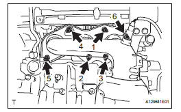
18. INSTALL NO. 2 MANIFOLD STAY
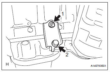
(a) Install the No. 2 manifold stay with the bolt and nut in the order shown in the illustration.
Torque: 34 N*m (347 kgf*cm, 25 ft.*lbf)
19. INSTALL OIL LEVEL GAUGE GUIDE SUBASSEMBLY
(a) Install 2 new O-rings to the oil level gauge guide.
(b) Apply a light coat of engine oil to the O-rings.
(c) Push in the oil level gauge guide end into the guide hole.
(d) Install the No. 1 oil level gauge guide with the bolt.
Torque: 21 N*m (214 kgf*cm, 15 ft.*lbf) (e) Install the No. 2 oil level gauge guide with the bolt.
Torque: 21 N*m (214 kgf*cm, 15 ft.*lbf) (f) Install the oil level gauge.
20. INSTALL EXHAUST MANIFOLD SUB-ASSEMBLY RH
(a) Install a new gasket as shown in the illustration.
(b) Install the exhaust manifold sub-assembly RH with the 6 nuts in the order shown in the illustration.
Torque: 21 N*m (214 kgf*cm, 15 ft.*lbf)
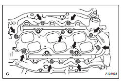
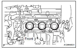
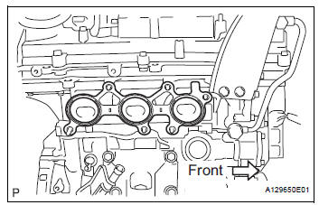
21. INSTALL INTAKE MANIFOLD
| NOTICE: DO NOT apply oil to the bolts listed below: |
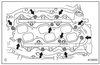
(a) Set a new gasket on each cylinder head.
NOTICE:
|
(b) Set the intake manifold on the cylinder heads.
(c) Install and tighten the 6 bolts and 4 nuts uniformly in several steps.
Torque: 21 N*m (214 kgf*cm, 15 ft.*lbf)
22. INSTALL NO. 2 ENGINE MOUNTING STAY RH
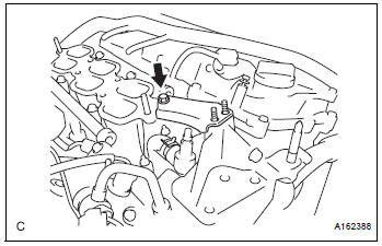
(a) Install the No. 2 mounting stay RH with the bolt.
Torque: 21 N*m (214 kgf*cm, 15 ft.*lbf)
23. INSTALL IGNITION COIL ASSEMBLY
(a) Install the 6 ignition coil assemblies with the 6 bolts.
Torque: 10 N*m (102 kgf*cm, 7 ft.*lbf)
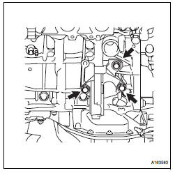
24. INSTALL INTAKE AIR SURGE TANK ASSEMBLY
NOTICE:
DO NOT apply oil to the bolts listed below:
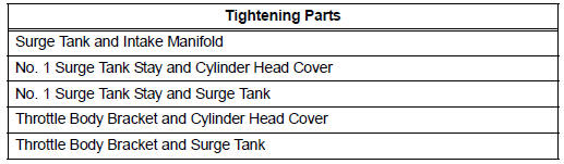 |
(a) Install a new gasket to the intake air surge tank.
(b) Using a 5 mm hexagon socket wrench, install the 4 bolts and 2 nuts.
Torque: Bolt 18 N*m (184 kgf*cm, 13 ft.*lbf) Nut 16 N*m (163 kgf*cm, 12 ft.*lbf)
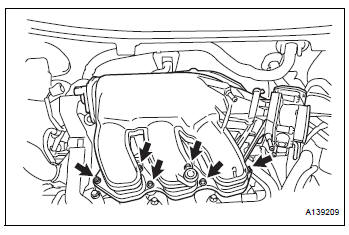
(c) Install the throttle body bracket, No. 1 surge tank stay and 4 bolts.
Torque: 21 N*m (214 kgf*cm, 15 ft.*lbf)
(d) Connect the connector.
(e) Connect the No. 1 ventilation hose.
(f) Install the clamp and connect the throttle with motor body assembly connector.
(g) Connect the vapor feed hose.
(h) Connect the 2 water by-pass hoses to the throttle with motor body assembly.
25. INSTALL VENTILATION HOSE
(a) Using pliers, grip the claws of the 2 clips and slide the 2 clips to the intake air surge tank assembly and ventilation valve.
26. INSTALL ENGINE HANGERS
(a) Install the 4 bolts, and 2 engine hangers.
27. REMOVE ENGINE STAND 28. INSTALL DRIVE PLATE AND RING GEAR SUBASSEMBLY (See page EM-13) 29. INSTALL AUTOMATIC TRANSAXLE ASSEMBLY (for 2WD)
HINT: See page AX-166.
30. INSTALL AUTOMATIC TRANSAXLE ASSEMBLY (for 4WD)
HINT: (See page AX-167).
31. INSTALL TRANSFER STIFFENER PLATE RH (See page AX-168)
32. INSTALL MANIFOLD STAY
(a) Install the bolt, nut, and manifold stay.
Torque: 34 N*m (347 kgf*cm, 25 ft.*lbf)
33. INSTALL ENGINE FRONT MOUNTING BRACKET (See page AX-167) 34. INSTALL STARTER ASSEMBLY (See page ST-13) 35. INSTALL ENGINE WIRE 36. INSTALL FRONT DRIVE SHAFT ASSEMBLY LH (See page DS-17) 37. INSTALL FRONT DRIVE SHAFT ASSEMBLY RH (for 2WD) (See page DS-17) 38. INSTALL FRONT DRIVE SHAFT ASSEMBLY RH (for 4WD) (See page DS-17) 39. INSTALL FRONT FRAME ASSEMBLY
(a) Install the engine mounting insulators RH and LH with the 2 nuts.
Torque: 95 N*m (969 kgf*cm, 70 ft.*lbf)
(b) Install the engine mounting insulator FR with the bolt.
Torque: 87 N*m (887 kgf*cm, 64 ft.*lbf)
(c) Install the engine mounting insulator RR with the 2 bolts.
Torque: 78 N*m (795 kgf*cm, 58 ft.*lbf)
(d) Connect the connector and clamp.
40. INSTALL POWER STEERING LINK (See page PS-39)
41. INSTALL FRONT STABILIZER BAR
HINT: (See page SP-36).
42. REMOVE ENGINE HANGERS
(a) Remove the 4 bolts and 2 engine hangers.
43. INSTALL VANE PUMP ASSEMBLY
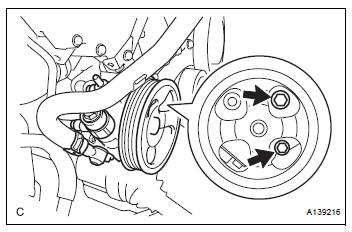
(a) Install the vane pump with the 2 bolts and nut.
Torque: 43 N*m (438 kgf*cm, 32 ft.*lbf)
(b) Install the 2 pressure feed tube clamp nuts.
Torque: 7.8 N*m (80 kgf*cm, 69 in.*lbf) (c) Connect the power steering oil pressure switch connector.
44. INSTALL ENGINE ASSEMBLY WITH TRANSAXLE
(a) Set the engine assembly with transaxle on the engine lifter.
(b) Install the engine assembly to the vehicle.
(c) Install the frame side rail plates RH and LH with the 6 bolts and 2 nuts.
Torque: A 85 N*m (867 kgf*cm, 63 ft.*lbf) B 32 N*m (329 kgf*cm, 24 ft.*lbf)
(d) Install the front suspension member brace rear RH and LH with the 6 bolts and 2 nuts.
Torque: A 85 N*m (867 kgf*cm, 63 ft.*lbf) B 32 N*m (329 kgf*cm, 24 ft.*lbf)
45. RECONNECT SUCTION HOSE SUB-ASSEMBLY (See page AC-231) 46. RECONNECT DISCHARGE HOSE SUB-ASSEMBLY (See page AC-232) 47. INSTALL STEERING INTERMEDIATE SHAFT SUBASSEMBLY (See page SR-10) 48. INSTALL FRONT AXLE ASSEMBLY LH (See page DS- 18) 49. INSTALL FRONT AXLE ASSEMBLY RH
HINT: Use the same procedures described for the LH side.
50. INSTALL FRONT SUSPENSION LOWER NO. 1 ARM LH (See page DS-18) 51. INSTALL FRONT SUSPENSION LOWER NO. 1 ARM RH
HINT: Use the same procedures described for the LH side.
52. INSTALL TIE ROD ASSEMBLY LH (See page DS-18) 53. INSTALL TIE ROD ASSEMBLY RH
HINT: Use the same procedures described for the LH side.
54. INSTALL FRONT SPEED SENSOR LH (See page DS- 18) 55. INSTALL FRONT SPEED SENSOR RH
HINT: Use the same procedures described for the LH side.
56. INSTALL FRONT AXLE HUB NUT LH (See page DS- 19) 57. INSTALL FRONT AXLE HUB NUT RH
HINT: Use the same procedures described for the LH side.
58. INSTALL FRONT STABILIZER LINK ASSEMBLY LH (See page DS-19) 59. INSTALL FRONT STABILIZER LINK ASSEMBLY RH
HINT: Use the same procedures described for the LH side.
60. INSTALL PROPELLER WITH CENTER BEARING SHAFT ASSEMBLY (See page PR-9) 61. FULLY TIGHTEN PROPELLER WITH CENTER BEARING SHAFT ASSEMBLY (See page PR-10) 62. INSTALL FRONT EXHAUST PIPE ASSEMBLY (for 2WD)
(a) Install the front exhaust pipe assembly (See page EX-4).
63. INSTALL FRONT EXHAUST PIPE ASSEMBLY (for 4WD)
(a) Install front exhaust pipe assembly (See page EX- 10).
64. INSTALL CENTER EXHAUST PIPE ASSEMBLY
(a) Install center exhaust pipe assembly (See page EX- 10).
65. CONNECT ENGINE WIRE
(a) Install the 2 bolts and 2 ground cables.
Torque: 8.4 N*m (85 kgf*cm, 74 in.*lbf)
(b) Install the bolt and 2 clamps to the body.
Torque: 8.4 N*m (85 kgf*cm, 74 in.*lbf)
(c) Connect the wire to the engine room junction block.
Then, install it with the nut.
Torque: 8.4 N*m (85 kgf*cm, 74 in.*lbf) (d) Install the engine wire to the body with the 2 nuts.
Torque: 8.4 N*m (85 kgf*cm, 74 in.*lbf)
66. CONNECT NO. 1 OIL RESERVOIR TO PUMP HOSE
(a) Using pliers, grip the claws of the clip and slide the clip to connect the No. 1 oil reservoir to pump hose to the oil reservoir tank.
67. CONNECT RETURN TUBE SUB-ASSEMBLY
(a) Using pliers, grip the claws of the 2 clips and slide the 2 clips to connect 2 return tube sub-assemblies.
| NOTICE: Take care not to damage the hose protector. |
68. CONNECT TRANSMISSION CONTROL CABLE ASSEMBLY
(a) Connect the control cable to the control cable clamp.
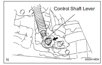
(b) Install the transmission control cable assembly to the control shaft lever with the nut.
Torque: 12 N*m (122 kgf*cm, 9 ft.*lbf)
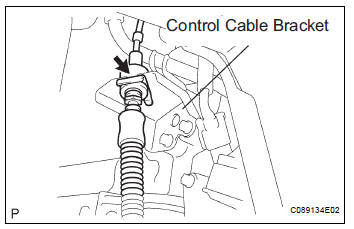
(c) Connect the transmission control cable assembly to the bracket with a new clip.
69. CONNECT FUEL TUBE SUB-ASSEMBLY
(a) Push in the fuel tube connector to the fuel pipe until the fuel tube makes a "click" sound.
NOTICE:
|
(b) Install the No. 1 fuel pipe clamp.
70. CONNECT NO. 1 OIL COOLER OUTLET HOSE
(a) Using pliers, grip the claws of the clip and slide the clip to connect the No. 1 oil cooler outlet hose to the No. 1 oil cooler outlet tube.
71. CONNECT NO. 1 OIL COOLER INLET HOSE
(a) Using pliers, grip the claws of the clip and slide the clip to connect the No. 1 oil cooler inlet hose to the No. 1 oil cooler inlet tube.
72. CONNECT HEATER WATER INLET HOSE B
(a) Using pliers, grip the claws of the clip and slide the clip to connect the heater water inlet hose to water outlet.
73. CONNECT HEATER WATER OUTLET HOSE B
(a) Using pliers, grip the claws of the clip and slide the clip to connect the heater water outlet hose to water outlet.
74. INSTALL RADIATOR INLET HOSE
(a) Using pliers, grip the claws of the clip and slide the clip to connect the radiator inlet hose to the water outlet.
75. INSTALL RADIATOR OUTLET HOSE
(a) Using pliers, grip the claws of the clip and slide the clip to connect the radiator outlet hose to the water inlet.
76. CONNECT UNION TO CHECK VALVE HOSE
(a) Using pliers, grip the claws of the clip and slide the clip to connect the union to check valve hose to the intake air surge tank assembly.
77. CONNECT NO. 1 FUEL VAPOR FEED HOSE
(a) Install the clamp and connect the No. 1 fuel vapor feed hose.
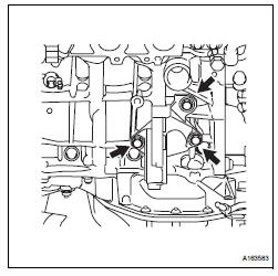
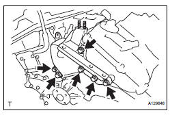
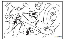
78. INSTALL ENGINE MOVING CONTROL ROD
(a) Temporarily install the engine moving control rod with the 3 bolts.
(b) First install the bolts A, and then the remaining bolt B.
Torque: 38 N*m (388 kgf*cm, 28 ft.*lbf)
79. INSTALL NO. 2 ENGINE MOUNTING STAY RH
(a) Temporarily install the No. 2 engine mounting stay RH with the bolt.
Torque: 38 N*m (388 kgf*cm, 28 ft.*lbf) (b) Tighten the 2 nuts.
Torque: 23 N*m (235 kgf*cm, 17 ft.*lbf)
80. INSTALL INTAKE AIR RESONATOR SUB-ASSEMBLY
(a) Install the intake air resonator with the bolt and clip.
Torque: 5.0 N*m (51 kgf*cm, 44 in.*lbf)
81. INSTALL AIR CLEANER BRACKET
(a) Remove the 2 bolts and air cleaner bracket.
Torque: 12 N*m (122 kgf*cm, 9 ft.*lbf)
82. INSTALL BATTERY
(a) Install the battery and battery tray.
(b) Install the battery clamp with the bolt and nut.
Torque: Bolt 9.0 N*m (92 kgf*cm, 80 in.*lbf) Nut 3.5 N*m (36 kgf*cm, 31 in.*lbf)
(c) Connect the positive battery terminal.
(d) Connect the negative battery terminal.
83. INSTALL AIR CLEANER CASE SUB-ASSEMBLY
(a) Install the air cleaner case with the 3 bolts.
Torque: 5.0 N*m (51 kgf*cm, 44 in.*lbf) (b) Connect the vacuum hose.
(c) Connect the vacuum switching valve connector.
84. INSTALL AIR CLEANER FILTER ELEMENT SUBASSEMBLY
(a) Install the air cleaner filter element sub-assembly.
85. INSTALL AIR CLEANER CAP SUB-ASSEMBLY (See page IT-5) 86. INSTALL NO. 1 AIR CLEANER INLET
(a) Install the No. 1 air cleaner inlet with the bolt.
Torque: 7.0 N*m (71 kgf*cm, 62 in.*lbf)
87. INSTALL NO. 2 AIR CLEANER INLET

(a) Install the No. 2 air cleaner inlet with the 2 clamps and 2 bolts.
Torque: 7.0 N*m (71 kgf*cm, 62 in.*lbf)
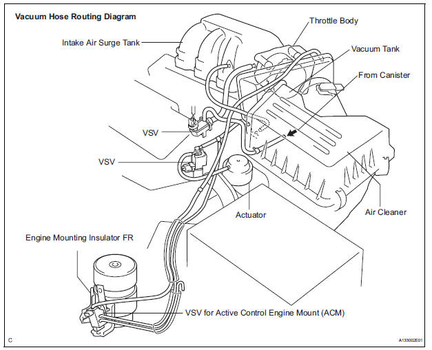
88. CONNECT VACUUM HOSES
89. INSTALL V-RIBBED BELT (See page EM-7)
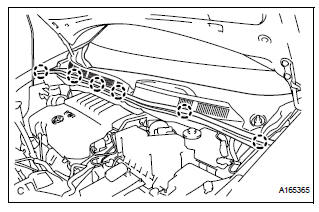
90. INSTALL FRONT OUTER COWL TOP PANEL SUBASSEMBLY
(a) Install the front outer cowl top panel sub-assembly with the 7 bolts.
Torque: 7.5 N*m (76 kgf*cm, 66 in.*lbf)
(b) Install the 2 clips.
(c) Install the fuel pump resistor with the nut.
Torque: 7.5 N*m (76 kgf*cm, 66 in.*lbf)
91. INSTALL NO. 1 COWL TOP TO COWL BRACE INNER
(a) Install the No. 1 cowl top to cowl brace inner.
Torque: 7.5 N*m (76 kgf*cm, 66 in.*lbf)
92. INSTALL FRONT WIPER MOTOR AND LINK (See page WW-6)
93. INSTALL COWL TOP VENTILATOR LOUVER SUBASSEMBLY
(a) Push the ventilator louver in the direction indicated by the arrow in the illustration. Attach the 6 claws to install the ventilator louver.
94. INSTALL WINDSHIELD WIPER ARM AND BLADE ASSEMBLY LH (See page WW-6) 95. INSTALL WINDSHIELD WIPER ARM AND BLADE ASSEMBLY RH (See page WW-7)
96. INSTALL FRONT WIPER ARM HEAD CAP
(a) Install the front wiper arm head caps.
97. INSTALL FRONT WHEELS Torque: 103 N*m (1050 kgf*cm, 76 ft.*lbf) 98. ADD ENGINE OIL (See page LU-6) 99. ADD ENGINE COOLANT (See page CO-7) 100.ADD AUTOMATIC TRANSAXLE FLUID 101.CHECK AUTOMATIC TRANSAXLE FLUID (See page AX-123) 102.ADD POWER STEERING FLUID 103.BLEED POWER STEERING FLUID (See page PS-6) 104.INSPECT FOR FUEL LEAK (See page FU-7) 105.INSPECT FOR ENGINE OIL LEAK 106.INSPECT FOR ENGINE COOLANT LEAK (See page CO-1) 107.INSPECT FOR EXHAUST GAS LEAK 108.CHECK SHIFT LEVER POSITION (See page AX-127) 109.CHECK AND ADJUST FRONT WHEEL ALIGNMENT
HINT: (See page SP-4).
110. CHECK IGNITION TIMING (See page EM-1) 111. CHECK ENGINE IDLE SPEED (See page EM-2) 112. CHECK CO/HC (See page EM-4) 113.CHECK FUNCTION OF THROTTLE BODY ASSEMBLY (See page ES-493) 114. INSTALL FRONT FENDER APRON SEAL RH
(a) Install the front fender apron seal RH with the 2 bolts and clip.
115. INSTALL FRONT FENDER APRON SEAL LH
(a) Install the front fender apron seal LH with the 2 bolts and clip.
116. INSTALL NO. 1 ENGINE UNDER COVER ASSEMBLY
(a) Install the No. 1 engine under cover sub-assembly with the 8 bolts and 4 clips.
117. INSTALL V-BANK COVER SUB-ASSEMBLY
(a) Fit the 3 retainers and install the V-bank cover.
118. CHECK ABS SPEED SENSOR SIGNAL BC-72 119. RESET MEMORY
HINT:
See page AX-16.
 Engine rear oil seal
Components
Removal
1. REMOVE AUTOMATIC TRANSAXLE ASSEMBLY (for
2WD)
HINT:
See page AX-163.
2. REMOVE AUTOMATIC TRANSAXLE ASSEMBLY (for
4WD)
HINT:
See page AX-167.
3. REMOVE DRIVE PLATE A ...
 Engine unit
COMPONENTS
...
Other materials:
Setting the vehicle speed
Press the “ON-OFF” button to
activate the cruise control.
Cruise control indicator will come
on*1 or will be displayed on the
multi-information display*2.
Press the button again to deactivate
the cruise control.
Accelerate or decelerate the
vehicle to the desired s ...
System Too Lean/ System Too Rich
DTC P0171 System Too Lean (Bank 1)
DTC P0172 System Too Rich (Bank 1)
DTC P0174 System Too Lean (Bank 2)
DTC P0175 System Too Rich (Bank 2)
DESCRIPTION
The fuel trim is related to the feedback compensation value, not to the basic
injection time. The fuel trim
consists of both the short-term ...
Short to B+ in Door System Communication
Bus Malfunction/ Short to GND in Door System Communication
Bus Malfunction
DTC B1214 Short to B+ in Door System Communication
Bus Malfunction
DTC B1215 Short to GND in Door System Communication
Bus Malfunction
DESCRIPTION
DTCs B1214 and B1215 are output when a short to +B or the body ground occurs
on the communication
bus. Detecting this condition disables all the ...
