Toyota Sienna Service Manual: Oxygen (A/F) Sensor Pumping Current Circuit
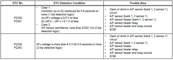
DTC P2238 Oxygen (A/F) Sensor Pumping Current Circuit Low (Bank 1 Sensor 1)
DTC P2239 Oxygen (A/F) Sensor Pumping Current Circuit High (Bank 1 Sensor 1)
DTC P2241 Oxygen (A/F) Sensor Pumping Current Circuit Low (Bank 2 Sensor 1)
DTC P2242 Oxygen (A/F) Sensor Pumping Current Circuit High (Bank 2 Sensor 1)
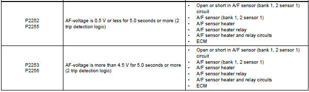
DTC P2252 Oxygen (A/F) Sensor Reference Ground Circuit Low (Bank 1 Sensor 1)
DTC P2253 Oxygen (A/F) Sensor Reference Ground Circuit High (Bank 1 Sensor 1)
DTC P2255 Oxygen (A/F) Sensor Reference Ground Circuit Low (Bank 2 Sensor 1)
DTC P2256 Oxygen (A/F) Sensor Reference Ground Circuit High (Bank 2 Sensor 1)
HINT:
- Although the DTC titles say oxygen sensor, these DTCs relate to the Air-Fuel Ratio (A/F) sensor.
- Sensor 1 refers to the sensor mounted in front of the Three-Way Catalytic Converter (TWC) and located near the engine assembly.
DESCRIPTION
Refer to DTC P2195
HINT:
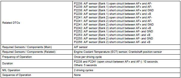
- DTC P2238, P2239, P2252 and P2253 indicate malfunctions related to the bank 1 A/F sensor circuit.
- DTC P2241, P2242, P2255 and P2256 indicate malfunctions related to the bank 2 A/F sensor circuit.
- Bank 1 refers to the bank that includes cylinder No. 1.
- Bank 2 refers to the bank that includes cylinder No. 2.
MONITOR DESCRIPTION
The Air-Fuel Ratio (A/F) sensor varies its output voltage in proportion to the air-fuel ratio. If the A/F sensor impedance (alternating current resistance) or voltage output deviates greatly from the standard range, the ECM determines that there is an open or short malfunction in the A/F sensor circuit.
MONITOR STRATEGY
TYPICAL ENABLING CONDITIONS
All:

P2238 and P2241 (open circuit between AF+ and AF-):
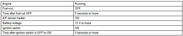
Others:

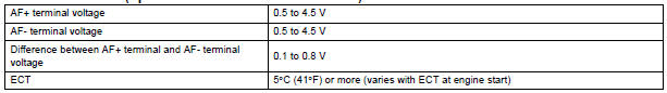
TYPICAL MALFUNCTION THRESHOLDS
P2238 and P2241 (Open circuit between AF+ and AF-):

P2238 and P2241 (Short circuit between AF+ and GND):

P2238 and P2241 (Short circuit between AF+ and AF-):

P2239 and P2242 (Short circuit between AF+ and +B):

P2252 and P2255 (Short circuit between AF- and GND):

P2253 and P2256 (Short circuit between AF- and +B):

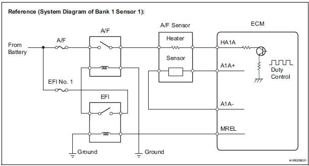
WIRING DIAGRAM
Refer to DTC P2195.
INSPECTION PROCEDURE
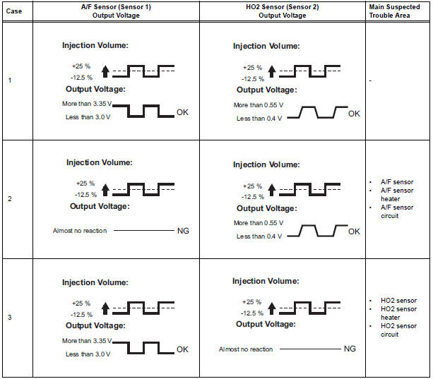
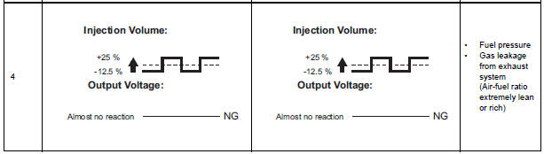
HINT: For use of the intelligent tester only: Malfunctioning areas can be identified by performing the A/F CONTROL function provided in the ACTIVE TEST. The A/F CONTROL function can help to determine whether the Air-Fuel Ratio (A/F) sensor, Heated Oxygen (HO2) sensor and other potential trouble areas are malfunctioning.
The following instructions describe how to conduct the A/F CONTROL operation using the intelligent tester.
- Connect the intelligent tester to the DLC3.
- Start the engine and turn the tester on.
- Warm up the engine at an engine speed of 2500 rpm for approximately 90 seconds.
- Select the following menu items on the tester: DIAGNOSIS / ENHANCED OBD II / ACTIVE TEST / A/ F CONTROL.
- Perform the A/F CONTROL operation with the engine in an idling condition (press the RIGHT or LEFT button to change the fuel injection volume).
- Monitor the voltage outputs of the A/F and HO2 sensors (AFS B1S1 and O2S B1S2 or AFS B2S1 and O2S B2S2) displayed on the tester.
HINT:
- The A/F CONTROL operation lowers the fuel injection volume by 12.5% or increases the injection volume by 25%.
- Each sensor reacts in accordance with increases and decreases in the fuel injection volume.
Standard voltage
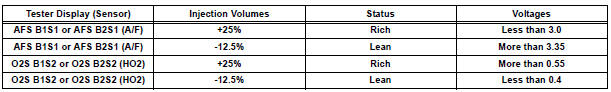
NOTICE: The Air-Fuel Ratio (A/F) sensor has an output delay of a few seconds and the Heated Oxygen (HO2) sensor has a maximum output delay of approximately 20 seconds.
Following the A/F CONTROL procedure enables technicians to check and graph the voltage outputs of both the A/F and HO2 sensors.
To display the graph, select the following menu items on the tester: DIAGNOSIS / ENHANCED OBD II / ACTIVE TEST / A/F CONTROL / USER DATA / AFS B1S1 and O2S B1S2 or AFS B2S1 and O2S B2S2. Press the YES button and then the ENTER button. Then press the F4 button.
HINT:
- Read freeze frame data using the intelligent tester. The ECM records vehicle and driving condition information as freeze frame data the moment a DTC is stored. When troubleshooting, freeze frame data can be helpful in determining whether the vehicle was running or stopped, whether the engine was warmed up or not, whether the air-fuel ratio was lean or rich, as well as other data recorded at the time of a malfunction.
- A low A/F sensor voltage could be caused by a rich air-fuel mixture. Check for conditions that would cause the engine to run rich.
- A high A/F sensor voltage could be caused by a lean air-fuel mixture. Check for conditions that would cause the engine to run lean.
1 INSPECT AIR FUEL RATIO SENSOR (HEATER RESISTANCE)
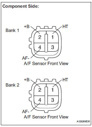
- Disconnect the A5 or A6 A/F sensor connector.
- Measure the resistance according to the value(s) in the table below.
Standard resistance: Bank 1
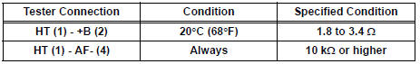
Bank 2
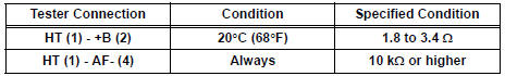
- Reconnect the A/F sensor connector.
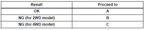
Result
2 INSPECT RELAY (A/F RELAY)
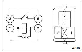
- Remove the A/F relay from the No. 6 engine room relay block.
- Measure the resistance according to the value(s) in the table below.
Standard resistance
- Reinstall the A/F relay
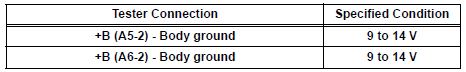
3 CHECK HARNESS AND CONNECTOR (A/F SENSOR - ECM)
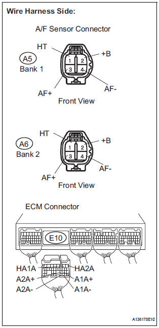
- Disconnect the A5 or A6 A/F sensor connector.
- Turn the ignition switch to the ON position.
- Measure the voltage according to the value(s) in the table below.
Standard voltage
- Turn the ignition switch off.
- Disconnect the E10 ECM connector.
- Measure the resistance according to the value(s) in the table below.
Standard resistance : Check for open
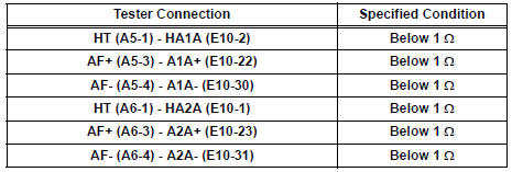
Check for short
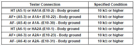
- Reconnect the ECM connector.
- Reconnect the A/F sensor connector.
REPLACE ECM
 Oxygen (A/F) Sensor Signal Stuck
DTC P2195 Oxygen (A/F) Sensor Signal Stuck Lean (Bank 1
Sensor 1)
DTC P2196 Oxygen (A/F) Sensor Signal Stuck Rich (Bank 1
Sensor 1)
DTC P2197 Oxygen (A/F) Sensor Signal Stuck Lean (Bank 2
Sensor ...
 Evaporative Emission System Switching Valve
Control Circuit High
Evaporative Emission System Switching Valve
Control Circuit High
DTC P2420 Evaporative Emission System Switching Valve
Control Circuit High
DTC SUMMARY
DESCRIPTION
The circuit description can be found in the EVAP (Evaporative Emission)
System.
INSPECTION ...
Other materials:
Initialization
1. RESET
Reset the power slide door system:
The power slide door ECU records the fully open
position of the power slide door in its memory and
the power slide door fully opens and closes based
on this memory. The power slide door cannot
operate without this memory. In the case wh ...
Diagnosis system
1. CHECK DLC3
The ECU uses the ISO 15765-4 for communication
protocol. The terminal arrangement of the DLC3
complies with SAE J1962 and matches the ISO
15765-4 format.
NOTICE:
*: Before measuring the resistance, leave the
vehicle as is for at least 1 minute and do not
opera ...
Precaution
NOTICE:
Perform the RESET MEMORY (AT initialization) when
replacing the automatic transaxle assembly, engine
assembly or ECM (See page AX-16).
Perform the REGISTRATION (VIN registration) when
replacing the ECM (See page ES-15).
HINT:
RESET MEMORY can not be ...
