Toyota Sienna Service Manual: Freeze frame data
1. FREEZE FRAME DATA
(a) The vehicle (sensor) status, stored during ABS and/ or VSC operation or at the time of an error code detection, can be displayed by the intelligent tester.
(b) Only one record of freeze frame data is stored and the freeze frame data generated during ABS and/or VSC operation are updated whenever the vehicle status is changed. Also, the number of the ignition switch is ON after the freeze frame data is stored can be stored up to 31 and it can be displayed. After storing the DTC, the freeze frame data is not updated.
HINT: If the ignition switch "ON" operation exceeds 31 times, "31"appears on the display.
(c) If a malfunction occurs, the freeze frame data is stored but the ABS actuation data is deleted.
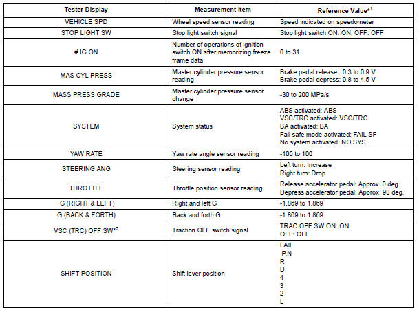
*1: If no conditions are specifically stated for "Idling", it means the shift lever is at N or P position, the A/C switch is OFF and all accessory switches are OFF.
*2: 2WD only
 Dtc check / clear
1. DTC CHECK/CLEAR (WHEN USING INTELLIGENT TESTER):
(a) DTC check
(1) Connect the intelligent tester to the DLC3.
(2) Turn the ignition switch to the ON position.
(3) Read the DTCs followi ...
 Data list / active test
1. DATA LIST
HINT:
With the intelligent tester connected to the DLC3 and the
ignition switch to the ON position, the ABS, TRAC and
VSC data list can be displayed. Follow the prompts on
the tester ...
Other materials:
Data list / active test
1. DATA LIST
HINT:
Using the intelligent tester to read the DATA LIST allows
the values or states of switches, sensor, actuators and
other items to be read without removing any parts. This
non-intrusive inspection can be very useful because
intermittent conditions or signals may be discovered
...
Window defogger switch
INSPECTION
1. INSPECT WINDOW DEFOGGER SWITCH
Check the defogger switch illuminates.
Standard
If the result is not as specified, replace the switch
assembly or bulb.
Check the defogger timer.
Connect the positive (+) lead from the battery
to terminal 2 and ...
Air outlet control servo motor
ON-VEHICLE INSPECTION
1. INSPECT AIR OUTLET CONTROL SERVO MOTOR
(a) Remove the air outlet control servo motor.
(b) Connect the positive (+) lead from the battery to
terminal 4 and negative (-) lead to terminal 5, then
check that the lever turns to "DEF" position.
(c) Connect ...
