Toyota Sienna Service Manual: Rear Speed Sensor RH Circuit
DESCRIPTION
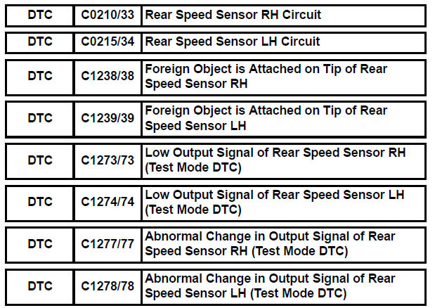
Refer to DTCs C0200/31, C0205/32, C1235/35, and C1236/36 (See page BC-17).
DTCs C1273/73 to C1278/78 can be deleted when the speed sensor sends a vehicle speed signal or the Test Mode ends. DTCs C1273/73 to C1278/78 are output only in the Test Mode.
HINT:
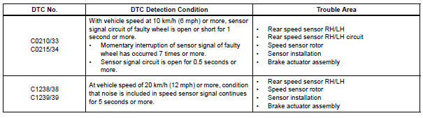
- DTC C0210/33 and C1238/38 are for the rear speed sensor RH.
- DTC C0215/34 and C1239/39 are for the rear speed sensor LH.
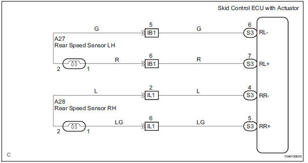
WIRING DIAGRAM
INSPECTION PROCEDURE
HINT: Start the inspection from step 1 when using the intelligent tester and start from step 3 when not using the intelligent tester.
1 READ VALUE OF INTELLIGENT TESTER (REAR SPEED SENSOR)
(a) Select the DATA LIST mode on the intelligent tester.
ABS: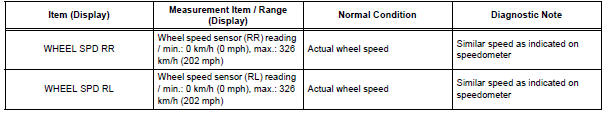
(b) Check that there is the speed value output from the speed sensor displayed on the intelligent tester and the speed value displayed on the speedometer are almost the same when driving the vehicle.
OK: The speed value output from the speed sensor displayed on the intelligent tester is the same as the actual vehicle speed.

2 PERFORM TEST MODE INSPECTION (SIGNAL CHECK)
(a) Clear the DTC (See page BC-10).
(b) Perform sensor signal check in TEST MODE PROCEDURE (See page BC-3).
OK: All Test Mode DTCs are erased.

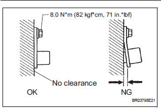
3 INSPECT REAR SPEED SENSOR INSTALLATION
(a) Turn the ignition switch off.
(b) Check the speed sensor installation.
OK: The installation nut is tightened properly.
There is no clearance between the sensor and the rear axle.
Torque: 8.0 N*m (82 kgf*cm, 71 in.*lbf)
NOTICE: Check the speed sensor signal after replacement (See page BC-3).

4 INSPECT SPEED SENSOR TIP
(a) Remove the rear speed sensor (See page BC-190).
(b) Check the sensor tip.
OK: No scratches or foreign matter on the sensor tip.
NOTICE: Check the speed sensor signal after cleaning or replacement (See page BC-3).
5 INSPECT HARNESS AND CONNECTOR (BETWEEN REAR SPEED SENSOR AND SKID CONTROL SENSOR WIRE)
(a) Install the rear speed sensor.
(b) Disconnect the rear speed sensor connector.
(c) Measure the resistance according to the value(s) in the table below.
Standard resistance
RH: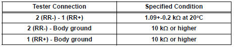
LH: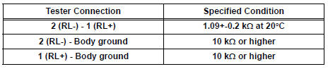
NOTICE: Check the speed sensor signal after replacement (See page BC-3).
6 CHECK HARNESS AND CONNECTOR (BETWEEN SKID CONTROL ECU AND REAR SPEED SENSOR)
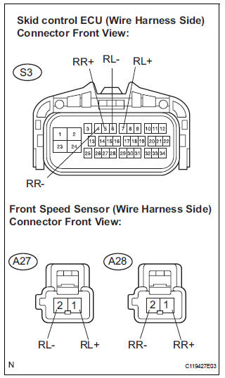
(a) Disconnect the skid control ECU connector.
(b) Measure the resistance according to the value(s) in the table below.
Standard resistance
RH: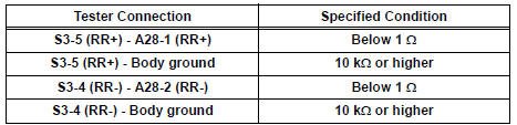
LH: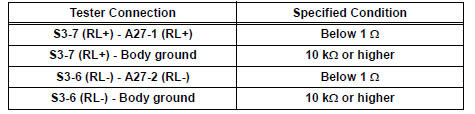

7 INSPECT SPEED SENSOR AND SENSOR ROTOR SERRATIONS
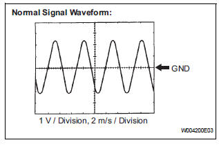
(a) Connect the oscilloscope to terminals FR+ - FR- or FL+ - FL- of the skid control ECU.
(b) Drive the vehicle at about 30 km/h (19 mph), and check the signal waveform.
OK: A waveform as shown in the figure should be output.
HINT:
- As vehicle speed (wheel rotation speed) increases, the width of the waveform narrows and the fluctuation in the output voltage becomes greater.
- When noise is identified in the waveform on the oscilloscope, error signals are generated due to rotor scratches, looseness or foreign matter attached to the speed sensor.

8 RECONFIRM DTC
(a) Clear the DTCs (See page BC-10).
(b) Drive the vehicle at a speed of approximately 32 km/h (20 mph) or more for 60 seconds or more.
(c) Check that the same DTCs are recorded (See page BC- 10).
HINT: Reinstall the sensors, connectors, etc. and restore the vehicle to its prior condition before rechecking for DTCs.
Result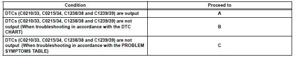

9 INSPECT SPEED SENSOR ROTOR
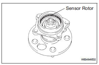
(a) Turn the ignition switch off.
(b) Remove the rear axle hub and bearing (See page AH- 16).
(c) Check the rotor.
OK: No scratches, oil, or foreign matter on the rotors.
NOTICE: Check the speed sensor signal after cleaning or replacement (See page BC-3).

REPLACE BRAKE ACTUATOR ASSEMBLY
 Front Speed Sensor RH Circuit
DESCRIPTION
The speed sensor detects wheel speed and transmits the appropriate signals to
the ECU. These signals
are used for control of the ABS control system. The front and rear rotors have ...
 SFR Solenoid Circuit
DESCRIPTION
The solenoid comes on when signals are received from the ECU and controls the
pressure acting on the
wheel cylinders, thus controlling brake force.
WIRING DIAGRAM
INSPECT ...
Other materials:
Removal
1. REMOVE REAR DOOR SCUFF PLATE LH
2. REMOVE REAR DOOR WEATHERSTRIP LH
3. REMOVE BACK DOOR WEATHERSTRIP
4. REMOVE BACK DOOR SCUFF PLATE
5. REMOVE QUARTER TRIM FRONT PANEL ASSEMBLY LH
6. REMOVE POWER POINT SOCKET ASSEMBLY
Release the 2 claw fittings and remove the power
point soc ...
Air outlet control servo motor (for rear air conditioning system)
ON-VEHICLE INSPECTION
1. INSPECT REAR AIR OUTLET CONTROL SERVO
MOTOR
(a) Inspect servo motor operation.
(1) Connect the positive (+) lead from the battery
to terminal 4 and negative (-) lead to terminal 5,
then check that the arm turns to "FOOT" side
smoothly.
(2) Connect t ...
Removal
1. REMOVE ENGINE ASSEMBLY WITH TRANSAXLE
HINT:
See page EM-26
2. REMOVE OIL LEVEL GAUGE GUIDE SUBASSEMBLY
(See page EM-39)
3. REMOVE NO. 1 OIL PIPE (See page EM-77)
4. REMOVE OIL PIPE (See page EM-77)
5. REMOVE CRANKSHAFT PULLEY (See page EM-79)
6. SEPARATE OIL COOLER PIPE
(a) Remove th ...
