Toyota Sienna Service Manual: How to proceed with troubleshooting
HINT:
The intelligent tester can be used in steps 2, 3, 4, 6 and 9.
1 VEHICLE BROUGHT TO WORKSHOP

2 CONNECT INTELLIGENT TESTER TO DLC3
HINT:
If the display indicates a communication fault in the tester, inspect the DLC3.

3 CHECK DTC AND FREEZE FRAME DATA
(a) Check for DTC(s) and freeze frame data (See page ES- 40).
HINT:
Record or print the DTCs and freeze frame data, if necessary.

4 CLEAR DTC AND FREEZE FRAME DATA
(a) Clear the DTC(s) and freeze frame data (See page ES- 40).

5 CONDUCT VISUAL INSPECTION

6 SET CHECK MODE DIAGNOSIS
(a) Set the check mode (See page ES-43).

7 CONFIRM PROBLEM SYMPTOMS
HINT:
If the engine does not start, perform steps 9 and 11 first.
Result 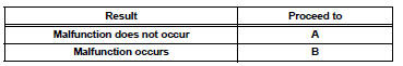

8 SIMULATE SYMPTOMS

9 CHECK FOR DTCS
(a) Check for DTCs (See page ES-39).
Result 

10 REFER TO DTC CHART
HINT:
Refer to the DTC chart (See page ES-56).

| GO TO STEP 13 |
11 CONDUCT BASIC INSPECTION
HINT:
Refer to "BASIC INSPECTION" (See page ES-13).
Result 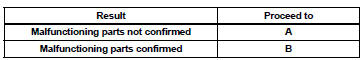

12 REFER TO PROBLEM SYMPTOMS TABLE
HINT:
Refer to "PROBLEM SYMPTOMS TABLE" (See page ES- 27).
Result 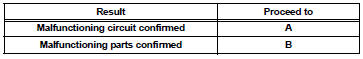

13 CHECK ECM POWER SOURCE CIRCUIT
HINT:
Refer to "ECM POWER SOURCE CIRCUIT" (See page ES- 437).

14 CONDUCT CIRCUIT INSPECTION
Result 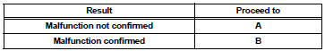

15 CHECK FOR INTERMITTENT PROBLEMS
HINT:
Refer to "CHECK FOR INTERMITTENT PROBLEMS" (See page ES-13).

| GO TO STEP 17 |
16 CONDUCT PARTS INSPECTION

17 IDENTIFY PROBLEM

18 ADJUST AND/OR REPAIR

19 CONDUCT CONFIRMATION TEST

END
 System diagram
...
 Check for intermittent problems
1. CHECK FOR INTERMITTENT PROBLEMS
HINT:
For use of the intelligent tester only:
Inspect the vehicle's ECM using check mode.
Intermittent problems are easier to detect with an
intelligent teste ...
Other materials:
ECU Power Source Circuit
DESCRIPTION
This circuit provides power to operate the theft deterrent (warning) ECU.
WIRING DIAGRAM
INSPECTION PROCEDURE
1 INSPECT FUSE (ECU-B)
Remove the ECU-B fuse from the engine room J/B.
Measure the resistance.
Standard resistance:
Below 1 Ω
2 CHECK INSTRUMENT PANEL ...
Precaution
1. Handling precautions on steering system
(a) Care must be taken when replacing parts. Incorrect
replacement could affect the performance of the
steering system and result in a driving hazard.
2. Handling precautions on srs airbag
system
(A) the vehicle is equipped with srs (supplemental
res ...
Removal
1. PRECAUTION
CAUTION: Be sure to read "PRECAUTION" thoroughly before
servicing.
2. DISCONNECT CABLE FROM NEGATIVE BATTERY
TERMINAL
CAUTION:
Wait for 90 seconds after disconnecting the cable to
prevent the airbag working.
3. PLACE FRONT WHEELS FACING STRAIGHT AHEAD
4. REMOVE STEE ...
