Toyota Sienna Service Manual: Inspection
1. INSPECT CHARCOAL CANISTER ASSEMBLY
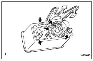
(a) Visually check the charcoal canister for cracks or damage.
If cracks or damage are found, replace the charcoal canister assembly.
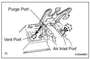
(b) Check charcoal canister operation.
(1) With the purge port closed, blow 1.67 kPa (17.0 gf/cm2, 0.24 psi) of air into the vent port, and check that air flows from the air inlet port.
If the result is not as specified, replace the charcoal canister assembly.
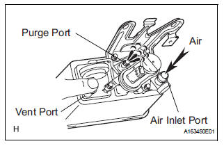
(2) With the vent port closed, blow 1.10 kPa (11.2 gf/cm2, 0.16 psi) of air to the air inlet port, and check that air flows from the purge port.
If the result is not as specified, replace the charcoal canister assembly.
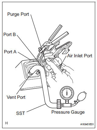
(c) Check for air leakage.
(1) Remove the air hose between ports A and B.
(2) Connect SST (pressure gauge) to the vent port of the charcoal canister.
SST 09992-00242 (3) While holding port B, with the purge port and the air inlet port closed and port A open, apply 19.6 kPa (0.2 kgf/cm2, 2.81 psi) of pressurized air into the vent port, then confirm that pressure is retained for 1 minute.
If the result is not as specified, replace the charcoal canister assembly.
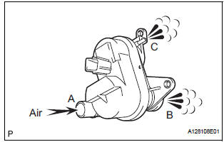
(d) Check the leak detection pump.
(1) Remove the detection pump from the charcoal canister.
(2) Check that air flows from port A to B and then C.
If the result is not as specified, replace the charcoal canister assembly.
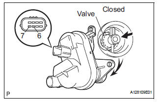
(3) Connect the positive (+) lead to terminal 7 and the negative (-) lead to terminal 6.
(4) Check that the valve is closed.
If the result is not as specified, replace the charcoal canister assembly.
(5) Install the detection pump.
 Removal
1. REMOVE CHARCOAL CANISTER PROTECTOR
(a) Remove the 6 bolts and charcoal canister protector.
2. REMOVE CHARCOAL CANISTER ASSEMBLY
(a) Disconnect the fuel tank vent hose from the
charcoal cani ...
 Installation
1. INSTALL CHARCOAL CANISTER ASSEMBLY
(a) Install the 3 bolts and charcoal canister.
Torque: 29 N*m (296 kgf*cm, 21 ft.*lbf)
(b) Connect the purge line hose to the charcoal
canister.
(c) ...
Other materials:
Ignition Coil "A" Primary
HINT:
These DTCs indicate malfunctions relating to the primary circuit.
If DTC P0351 is set, check the No. 1 ignition coil with igniter circuit.
If DTC P0352 is set, check the No. 2 ignition coil with igniter circuit.
If DTC P0353 is set, check the No. 3 ignition coil with igniter circ ...
Installation
1. INSTALL SEAT MEMORY SWITCH
2. INSTALL FRONT DOOR TRIM BOARD SUBASSEMBLY
LH
3. INSTALL POWER WINDOW REGULATOR MASTER
SWITCH ASSEMBLY
4. INSTALL FRONT DOOR INSIDE HANDLE BEZEL
PLUG LH
5. INSTALL FRONT DOOR LOWER FRAME BRACKET GARNISH LH
Engage the 4 claws to install the seat me ...
Throttle / Pedal Position Sensor / Switch "D" Circuit Range / Performance
HINT:
This DTC relates to the Accelerator Pedal Position (APP) sensor.
DESCRIPTION
Refer to DTC P2120 (See page ES-343).
MONITOR DESCRIPTION
The accelerator pedal position sensor is mounted on the accelerator pedal
bracket. The accelerator pedal
position sensor has 2 sensor elements ...
