Toyota Sienna Service Manual: Mass or Volume Air Flow Circuit Range / Performance Problem

DESCRIPTION
Refer to DTC P0100 (See page ES-116).
MONITOR DESCRIPTION
The MAF meter is a sensor that measures the amount of air flowing through the throttle valve. The ECM uses this information to determine the fuel injection time and to provide an appropriate air-fuel ratio.
Inside the MAF meter, there is a heated platinum wire which is exposed to the flow of intake air. By applying a specific electrical current to the wire, the ECM heats it to a specific temperature. The flow of incoming air cools both the wire and an internal thermistor, changing their resistance. To maintain a constant current value, the ECM varies the voltage applied to these components of the MAF meter. The voltage level is proportional to the air flow through the sensor, and the ECM uses it to calculate the intake air volume.
If there is a defect in the sensor, or an open or short in the circuit, the voltage level deviates from the normal operating range. The ECM interprets this deviation as a malfunction in the MAF meter and sets the DTC.
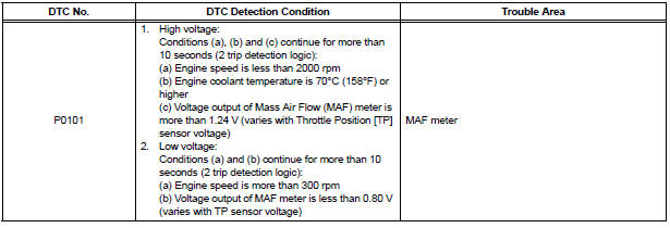
Example: If the voltage is more than 2.2 V, or less than 0.73 V while idling, the ECM determines that there is a malfunction in the MAF meter and sets the DTC.
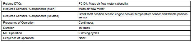
MONITOR STRATEGY
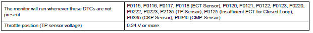
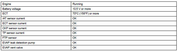
TYPICAL ENABLING CONDITIONS
TYPICAL MALFUNCTION THRESHOLDS

WIRING DIAGRAM
Refer to DTC P0100 (See page ES-118).
INSPECTION PROCEDURE
HINT:
Read freeze frame data using the intelligent tester. The ECM records vehicle and driving condition information as freeze frame data the moment a DTC is stored. When troubleshooting, freeze frame data can be helpful in determining whether the vehicle was running or stopped, whether the engine was warmed up or not, whether the air-fuel ratio was lean or rich, as well as other data recorded at the time of a malfunction.
1 CHECK ANY OTHER DTCS OUTPUT (IN ADDITION TO DTC P0101)
(a) Connect the intelligent tester to the DLC3.
(b) Turn the ignition switch to the ON position.
(c) Turn the tester on.
(d) Select the following menu items: DIAGNOSIS / ENHANCED OBD II / DTC INFO / CURRENT CODES.
(e) Read the DTCs.
Result 
HINT: If any DTCs other than P0101 are output, troubleshoot those DTCs first.

GO TO DTC CHART (See page ES-56)
 Mass or Volume Air Flow Circuit
DESCRIPTION
The Mass Air Flow (MAF) meter is a sensor that measures the amount of air
flowing through the throttle
valve. The ECM uses this information to determine the fuel injection time and ...
 Intake Air Temperature Circuit
DESCRIPTION
The Intake Air Temperature (IAT) sensor, mounted on the Mass Air Flow (MAF)
meter, monitors the IAT.
The IAT sensor has a built-in thermistor with a resistance that varies accord ...
Other materials:
ACC Power Source Circuit
DESCRIPTION
This circuit supplies power to the A/C amplifier and the illumination for the
clock.
WIRING DIAGRAM
INSPECTION PROCEDURE
1 INSPECT FUSE (ECU ACC)
(a) Remove the ECU ACC fuse from the engine room relay
block.
(b) Measure the resistance according to the value(s) in the
tab ...
Parts location
SYSTEM DIAGRAM
HINT:
The tire pressure warning valve and transmitter sends
information on the temperature inside the tire, the ID, and the
tire pressure. ...
Torque Converter Clutch Solenoid Circuit
DESCRIPTION
The shift solenoid valve DSL is turned "ON" and "OFF" by signals from the ECM
in order to control the
hydraulic pressure operation, the lock-up relay valve, which then controls
operation of the lock-up clutch.
MONITOR DESCRIPTION
Torque converter lock-up i ...
