Toyota Sienna Service Manual: Intermediate Shaft Speed Sensor "A"
DESCRIPTION
This sensor detects the rotation speed of the counter gear. By comparing the
counter gear speed signal
(NC) with the direct clutch speed sensor signal (NT), the ECM detects the shift
timing of the gears and
appropriately controls the engine torque and hydraulic pressure according to
various conditions. Thus
smooth gear shifting is performed.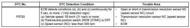
Reference (Using an oscilloscope):
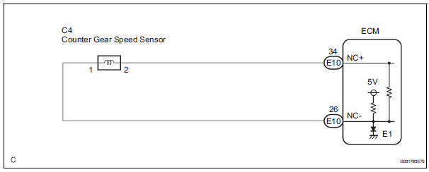
Check the waveform between terminals NC+ and NC- of the ECM connector.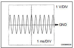
Standard: Refer to the illustration.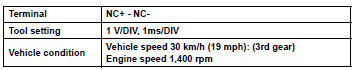
MONITOR DESCRIPTION
The NC terminal of the ECM detects a revolution signal from the speed sensor (NC) (counter gear rpm).
The ECM calculates a gearshift comparing the speed sensor (NT) with the speed sensor (NC).
While the vehicle is operating in 2nd, 3rd, 4th or 5th gear in the shift position of D, if the counter gear revolution is less than 300 rpm *1although the output shaft revolution is more than 1,000 rpm *2, the ECM detects the trouble, illuminates the MIL and stores the DTC.
*1: Pulse is not output or is irregularly output.
*2: The vehicle speed is 50 km/h (31 mph) or more.
MONITOR STRATEGY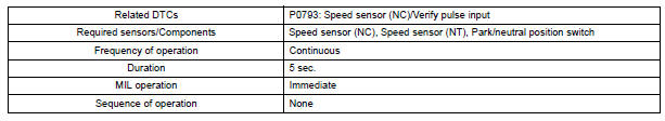
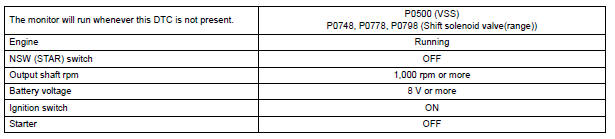
TYPICAL ENABLING CONDITIONS
TYPICAL MALFUNCTION THRESHOLDS

COMPONENT OPERATING RANGE
WIRING DIAGRAM
INSPECTION PROCEDURE
HINT: Using the intelligent tester to read the DATA LIST allows the values or states of switches, sensors, actuators and other items to be read without removing any parts. This non-intrusive inspection can be very useful because intermittent conditions or signals may be discovered before parts or wiring is disturbed. Reading the DATA LIST information early in troubleshooting is one way to save diagnostic time.
1. READ DATA LIST
(a) Warm up the engine.
(b) Turn the ignition switch off.
(c) Connect the intelligent tester together with the CAN VIM (controller area network vehicle interface module) to the DLC3.
(d) Turn the ignition switch to the ON position.
(e) Turn on the tester.
(f) Select the item "DIAGNOSIS / ENHANCED OBD II / DATA LIST".
(g) According to the display on the tester, read the "DATA LIST".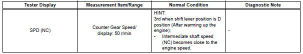
HINT:
- SPD (NC) is always 0 while driving: Open or short in the sensor or circuit.
- SPD (NC) is always more than 0 and less than 300 rpm while driving the vehicle at 50 km/h (31 mph) or more: Sensor trouble, improper installation, or intermittent connection trouble of the circuit.
1 INSPECT SPEED SENSOR INSTALLATION
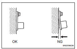
(a) Check the speed sensor installation.
OK: The installation bolt is tightened properly and there is no clearance between the sensor and transaxle case.


2 INSPECT SPEED SENSOR (NC)
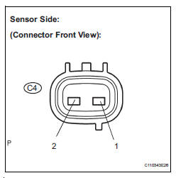
(a) Disconnect the speed sensor connector from the transaxle.
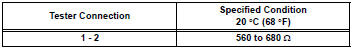
(b) Measure the resistance according to the value(s) in the table below.
Standard resistance


3 CHECK HARNESS AND CONNECTOR (SPEED SENSOR - ECM)
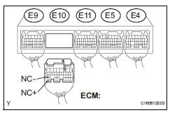
(a) Connect the speed sensor connector.
(b) Disconnect the ECM connector.
(c) Measure the resistance according to the value(s) in the table below.
Standard resistance
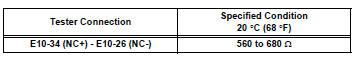
(d) Measure the resistance according to the value(s) in the table below.
Standard resistance (Check for short)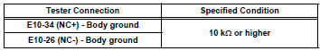

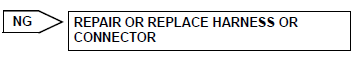
REPLACE ECM
 Pressure Control Solenoid "B" Electrical (Shift
Solenoid Valve SL2)
Pressure Control Solenoid "B" Electrical (Shift
Solenoid Valve SL2)
DESCRIPTION
Shifting from 1st to 5th is performed in combination with "ON" and "OFF"
operation of the shift solenoid
valves SL1, SL2, SL3, S4 and SR which are controlled by ...
 Pressure Control Solenoid "C" Performance (Shift
Solenoid Valve SL3)
Pressure Control Solenoid "C" Performance (Shift
Solenoid Valve SL3)
SYSTEM DESCRIPTION
The ECM uses signals from the vehicle speed sensor to detect the actual gear
position (1st, 2nd, 3rd, 4th
or 5th gear).
Then the ECM compares the actual gear with the shift s ...
Other materials:
Operation check
NOTICE: Inspection should be started after conforming that
the items listed in the "CUSTOMIZE PARAMETER" for the power back door system
have defaulted to the initial settings
1. CHECK OPENING OPERATION
Conditions necessary for the power back door to
open:
Power back d ...
Drive shaft system
PRECAUTION
1. NOTICE OF REMOVING AND INSTALLING FRONT
DRIVE SHAFT ASSEMBLY RH
(a) When removing and installing the front drive shaft
assembly RH in a 4WD vehicle, be sure to first drain
all the transaxle oil and transfer oil. If removal and
installation is carried out without draining these oi ...
Insufficient Coolant Temperature for Closed
Loop Fuel Control
DTC P0125 Insufficient Coolant Temperature for Closed
Loop Fuel Control
DESCRIPTION
Refer to DTC P0115
DTC No.
DTC Detection Condition
Trouble Area
P0125
Engine coolant temperature (ECT) does not reach
closed-loop enabling temperature for 20 minutes (t ...
