Toyota Sienna Service Manual: Crankshaft Position Sensor
DESCRIPTION
The Crankshaft Position (CKP) sensor system consists of a CKP sensor plate and a pickup coil. The sensor plate has 34 teeth and is installed on the crankshaft. The pickup coil is made of an iron core and a magnet.
The sensor plate rotates as each tooth passes through the pickup coil, and a pulse signal is created. The pickup coil generates 34 signals per engine revolution. Based on these signals, the ECM calculates the crankshaft position and engine RPM. Using these calculations, the fuel injection time and ignition timing are controlled.
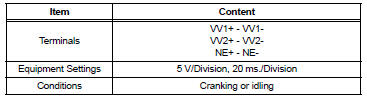
Reference: Inspection using an oscilloscope
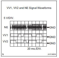
HINT:
- The correct waveform is shown in the illustration
- VV1+ and VV2+ stand for the VVT sensor signal, and NE+ stands for the
CKP sensor signal.
MONITOR DESCRIPTION
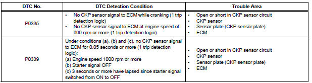
If there is no signal from the CKP sensor despite the engine revolving, the ECM interprets this as a malfunction of the sensor.
If the malfunction is not repaired successfully, a DTC is set 10 seconds after the engine is next started.
MONITOR STRATEGY
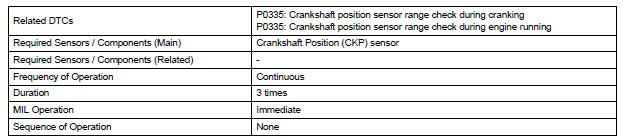
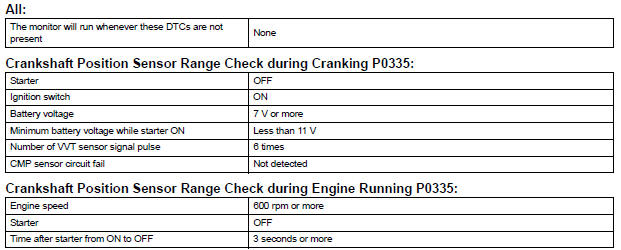
TYPICAL ENABLING CONDITIONS
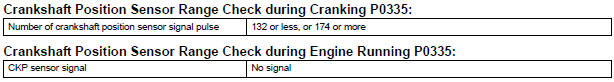
TYPICAL MALFUNCTION THRESHOLDS
COMPONENT OPERATING RANGE

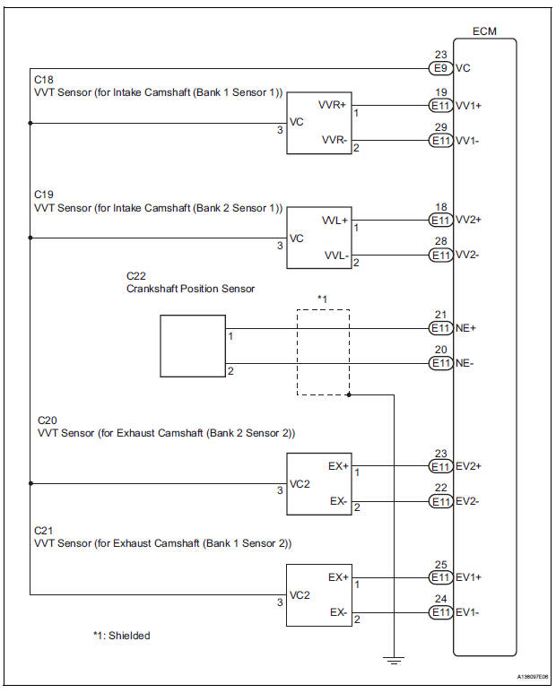
WIRING DIAGRAM
INSPECTION PROCEDURE
HINT:
- If no problem is found by this diagnostic troubleshooting procedure, troubleshoot the engine mechanical systems.
- Check the engine speed. The engine speed can be checked by using the intelligent tester. Perform the following procedure:
(a) Connect the intelligent tester to the DLC3.
(b) Start the engine.
(c) Turn the tester on.
(d) Select the following menu items: DIAGNOSIS / ENHANCED OBD II / DATA LIST / PRIMARY / ENGINE SPD.
The engine speed may be indicated as zero despite the engine revolving normally. This is caused by a lack of NE signals from the Crankshaft Position (CKP) sensor. Alternatively, the engine speed may be indicated as lower than the actual engine speed, if the CKP sensor voltage output is insufficient.
- Read freeze frame data using the intelligent tester. The ECM records vehicle and driving condition information as freeze frame data the moment a DTC is stored. When troubleshooting, freeze frame data can be helpful in determining whether the vehicle was running or stopped, whether the engine was warmed up or not, whether the air-fuel ratio was lean or rich, as well as other data recorded at the time of a malfunction.
1 INSPECT CRANKSHAFT POSITION SENSOR (RESISTANCE)
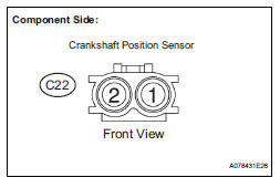
(a) Disconnect the C22 Crankshaft Position (CKP) sensor connector.
(b) Measure the resistance according to the value(s) in the table below.
Standard resistance 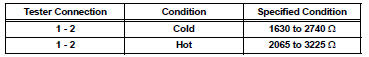
HINT:
Terms "cold" and "hot" refer to the temperature of the coils. "Cold" means approximately -10 to 50°C (14 to 122°F). "Hot" means approximately 50 to 100°C (122 to 212°F).
(c) Reconnect the CKP sensor connector

2 CHECK HARNESS AND CONNECTOR (CRANKSHAFT POSITION SENSOR - ECM)
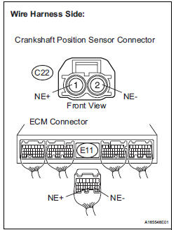
(a) Disconnect the C22 CKP sensor connector.
(b) Disconnect the E11 ECM connector.
(c) Measure the resistance according to the value(s) in the table below.
Standard resistance :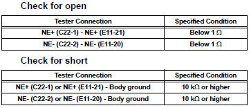
(d) Reconnect the ECM connector.
(e) Reconnect the CKP sensor connector.

3 CHECK SENSOR INSTALLATION (CRANKSHAFT POSITION SENSOR)
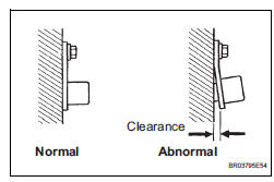
(a) Check the CKP sensor installation condition.
OK: Sensor is installed correctly.

4 CHECK CRANKSHAFT POSITION SENSOR PLATE (TEETH OF SENSOR PLATE)
(a) Check the teeth of the sensor plate.
OK: Sensor plate does not have any cracks or deformation.


REPLACE ECM (See page ES-498)
 Knock Sensor 1 Circuit Low Input
DESCRIPTION
A flat type knock sensor (non-resonant type) has a structure that can detect
vibrations over a wide band of
frequencies: between approximately 6 kHz and 15 kHz.
Knock sensors ar ...
 Camshaft Position Sensor "A" Circuit
DESCRIPTION
The intake camshaft's Variable Valve Timing (VVT) sensor (G signal) consists
of a magnet and MRE
(Magneto Resistance Element).
The VVT camshaft drive gear has a sensor plate wit ...
Other materials:
Personal/interior
lights
Front
Turns the light on/off
Rear
Turns the light on/off
When the personal/interior light main switch is in the off position, the
rear personal lights will not turn on even if the switch is on.
Type A
Type B
...
Oxygen (A/F) Sensor Heater Control Circuit
Low/ Oxygen (A/F) Sensor Heater Control Circuit
High
DTC P0031 Oxygen (A/F) Sensor Heater Control Circuit
Low (Bank 1 Sensor 1)
DTC P0032 Oxygen (A/F) Sensor Heater Control Circuit
High (Bank 1 Sensor 1)
DTC P0051 Oxygen (A/F) Sensor Heater Control Circuit
Low (Bank 2 Sensor 1)
DTC P0052 Oxygen (A/F) Sensor Heater Control Circuit
High (Bank 2 S ...
Side Airbag Sensor Assembly RH Circuit Malfunction
DTC B1140/32 Side Airbag Sensor Assembly RH Circuit Malfunction
DESCRIPTION
The side airbag sensor RH circuit consists of the center airbag sensor
assembly and side airbag sensor
RH.
If the center airbag sensor assembly receives signals from the side airbag
sensor RH, it judges whether or
...
