Toyota Sienna Service Manual: Mute Signal Circuit between Radio and Navigation Assembly and Television Display Assembly
DESCRIPTION
The radio and navigation assembly controls the volume according to the MUTE signal from the television display assembly.
The MUTE signal is sent to reduce noise and a popping sound generated when switching the mode, etc.
If there is an open in the circuit, noise can be heard from the speakers when changing the sound source.
If there is a short in the circuit, even though the radio and navigation assembly is normal, no sound or only an extremely small sound can be produced.
WIRING DIAGRAM
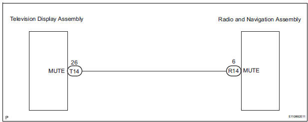
INSPECTION PROCEDURE
1 INSPECT TELEVISION DISPLAY ASSEMBLY
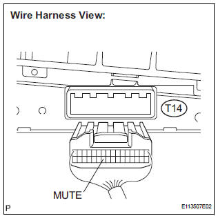
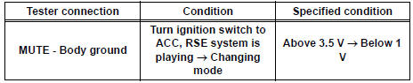
- Measure the voltage according to the value(s) in the table below.
Standard voltage
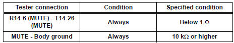
2 CHECK HARNESS AND CONNECTOR (RADIO AND NAVIGATION ASSEMBLY - TELEVISION DISPLAY ASSEMBLY)
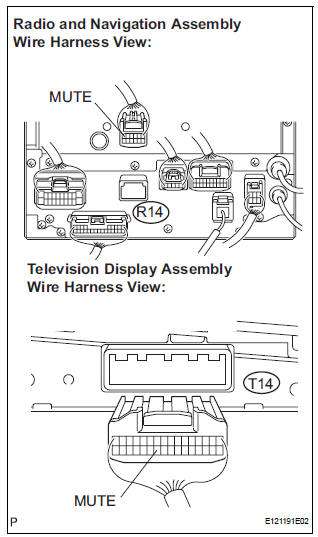
- Disconnect the radio and navigation assembly R14 connector and television display assembly T14 connector.
- Measure the resistance according to the value(s) in the table below.
Standard resistance
3 REPLACE TELEVISION DISPLAY ASSEMBLY
- Replace the television display assembly and check if it operates normally.
OK: The navigation system operates normally.
REPLACE RADIO AND NAVIGATION ASSEMBLY
 Sound Signal Circuit between Radio and Navigation Assembly and
Stereo Jack Adapter
Sound Signal Circuit between Radio and Navigation Assembly and
Stereo Jack Adapter
DESCRIPTION
The stereo jack adapter sends an external device sound signal to the radio
and navigation assembly
through this circuit.
The sound signal that has been sent is amplified by the ster ...
 Mute Signal Circuit between Radio and Navigation Assembly and
Stereo Component Amplifier
Mute Signal Circuit between Radio and Navigation Assembly and
Stereo Component Amplifier
DESCRIPTION
This circuit sends a signal to the stereo component amplifier to mute noise.
Because of that, the noise
produced by changing the sound source ceases.
If there is an open in the circ ...
Other materials:
Removal
1. REMOVE REAR DOOR SCUFF PLATE
2. REMOVE REAR DOOR WEATHERSTRIP
3. REMOVE BACK DOOR WEATHERSTRIP
4. REMOVE BACK DOOR SCUFF PLATE
5. REMOVE FRONT QUARTER TRIM PANEL ASSEMBLY
Remove the floor anchor cover.
Remove the bolt and disconnect the No. 2 rear seat
outer belt assem ...
Opening the back door from outside the vehicle
Back door opener
Raise the back door while
pressing the back door opener
to release the lock to open the
back door.
Wireless remote control (vehicles with power back door)
Press and hold the switch to open/close the power back door
Vehicles without a smart key
system
Vehicl ...
Seat heaters
For driverŌĆÖs seat
For front passengerŌĆÖs seat
On
The indicator light comes on.
Adjusts the seat temperature
The further you move the dial
upward, the warmer the seat
becomes.
The seat heaters can be used when the engine switch is in the ŌĆ£ONŌĆØ
position
(vehicles ...
