Toyota Sienna Service Manual: Mute Signal Circuit between Radio and Navigation Assembly and Stereo Component Amplifier
DESCRIPTION
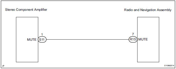
This circuit sends a signal to the stereo component amplifier to mute noise. Because of that, the noise produced by changing the sound source ceases.
If there is an open in the circuit, noise can be heard from the speakers when changing the sound source.
If there is a short in the circuit, even though the stereo component amplifier is normal, no sound, or only an extremely small sound, can be produced.
WIRING DIAGRAM
INSPECTION PROCEDURE
1 INSPECT STEREO COMPONENT AMPLIFIER
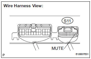
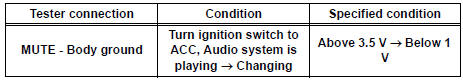
- Measure the voltage according to the value(s) in the table below.
Standard voltage
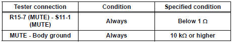
2 CHECK HARNESS AND CONNECTOR (RADIO AND NAVIGATION ASSEMBLY - STEREO COMPONENT AMPLIFIER)
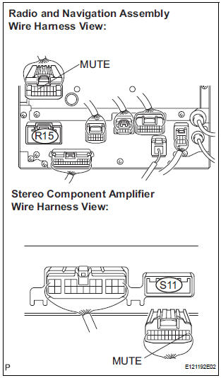
- Disconnect the radio and navigation assembly connector R15 and television display assembly connector S11.
- Measure the resistance according to the value(s) in the table below.
Standard resistance
3 REPLACE STEREO COMPONENT AMPLIFIER
- Replace the stereo component amplifier and check if it operates normally.
OK: The navigation system operates normally
REPLACE RADIO AND NAVIGATION ASSEMBLY
 Mute Signal Circuit between Radio and Navigation Assembly and
Television Display Assembly
Mute Signal Circuit between Radio and Navigation Assembly and
Television Display Assembly
DESCRIPTION
The radio and navigation assembly controls the volume according to the MUTE
signal from the television
display assembly.
The MUTE signal is sent to reduce noise and a popping sound ...
 AVC-LAN Circuit
DESCRIPTION
Each unit of the navigation system connected to the AVC-LAN (communication
bus) transfers the signal of
each switch by communication.
When a short to +B or short to ground occurs in ...
Other materials:
Inspection
1. INSPECT MULTIPLE DISC CLUTCH HUB
(a) Using a dial indicator, measure the inside diameter
of the forward clutch hub bushing
Standard inside diameter:
23.025 to 23.046 mm (0.9065 to 0.9073 in.)
Maximum inside diameter:
23.09 mm (0.9091 in.)
NOTICE:
Check the contact surface of ...
Short in Side Squib LH Circuit
DTC B0115/47 Short in Side Squib LH Circuit
DESCRIPTION
The side squib LH circuit consists of the center airbag sensor assembly and
the front seat side airbag
assembly LH.
This circuit instructs the SRS to deploy when deployment conditions are met.
DTC B0115/47 is recorded when a short ci ...
Basic inspection
When a malfunction is not confirmed by the DTC check,
troubleshooting should be carried out in all circuits
considered to be possible causes of the problem. In many
cases, by carrying out the basic engine check shown in the
following flowchart, the location of the problem can be found
quickly a ...
