Toyota Sienna Service Manual: Mute Signal Circuit between Radio Receiver and Stereo Component Amplifier
DESCRIPTION
This circuit sends a signal to the stereo component amplifier to mute noise. Because of that, the noise produced by changing the sound source ceases.
If there is an open in the circuit, noise can be heard from the speakers when changing the sound source.
If there is a short in the circuit, even though the stereo component amplifier is normal, no sound, or only an extremely small sound, can be produced.
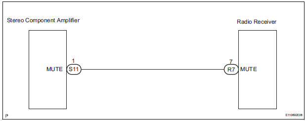
WIRING DIAGRAM
INSPECTION PROCEDURE
1 INSPECT STEREO COMPONENT AMPLIFIER
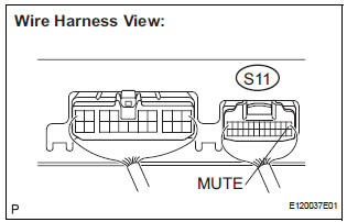
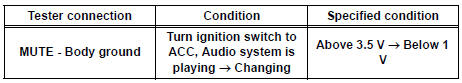
- Measure the voltage according to the value(s) in the table below.
Standard voltage
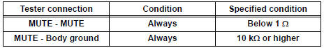
2 CHECK HARNESS AND CONNECTOR (RADIO RECEIVER - STEREO COMPONENT AMPLIFIER)
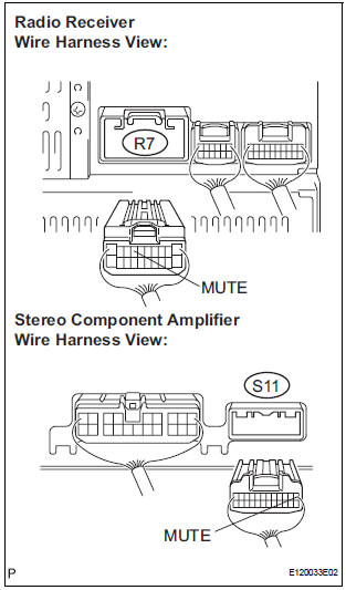
- Disconnect the radio receiver connector R7 and stereo component amplifier connector S11.
- Measure the resistance according to the value(s) in the table below.
Standard resistance
3 REPLACE STEREO COMPONENT AMPLIFIER
- Replace the stereo component amplifier and check if the audio system operates normally.
OK: The audio system operates normally.
REPLACE RADIO RECEIVER
 Sound Signal Circuit between Radio Receiver and Stereo Jack Adapter
DESCRIPTION
The stereo jack adapter sends an external device sound signal to the radio
receiver through this circuit.
The sound signal that has been sent is amplified by the stereo component
a ...
 Mute Signal Circuit between Radio Receiver and Television Display
Assembly
Mute Signal Circuit between Radio Receiver and Television Display
Assembly
DESCRIPTION
The radio receiver controls the volume according to the MUTE signal from the
television display
assembly.
The MUTE signal is sent to reduce noise and a popping sound generated when ...
Other materials:
Taillight Relay Circuit
DESCRIPTION
The Multiplex network body ECU controls TAIL relay when signal is received
from headlight dimmer
switch assembly.
WIRING DIAGRAM
INSPECTION PROCEDURE
1 PERFORM ACTIVE TEST BY INTELLIGENT TESTER
Connect the intelligent tester to DLC3.
Turn the ignition switch ON and ...
Display Signal Circuit between Video Terminal and Television Display
DESCRIPTION
This is the display signal circuit from the video terminal to the television
display assembly.
WIRING DIAGRAM
INSPECTION PROCEDURE
1 CHECK HARNESS AND CONNECTOR (TELEVISION DISPLAY ASSEMBLY - VIDEO
TERMINAL)
Disconnect the connectors from the video terminal and
tele ...
Installation
1. INSTALL REAR NO. 1 SEAT ASSEMBLY CENTER
Place the seat in the cabin.
NOTICE:
Be careful not to damage the body.
Install the rear seat.
Install the seat belt anchor plate with the bolt.
Torque: 42 N*m (428 kgf*cm, 31 ft.*lbf)
Install the headrest.
...
