Toyota Sienna Service Manual: Fuel Pump Primary Circuit

DESCRIPTION
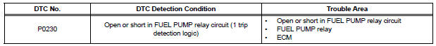
- This DTC is designed to detect a malfunction in the fuel pump (FUEL PUMP) relay circuit. When the system is normal, the battery voltage is applied to FPR terminal of the ECM while the FUEL PUMP relay is turned OFF. If the battery voltage is not applied to the FPR terminal while the FUEL PUMP relay is OFF, the ECM interprets this as a malfunction. The ECM then illuminates the MIL and sets a DTC.
- The FUEL PUMP relay switches the fuel pump speed according to the engine
conditions. The fuel
pump operates when the ECM receives the starter-operating signal (STA) and
crankshaft-rotating
signal (NE). The FUEL PUMP relay is turned ON while the engine is idling or
operating at low load.
This causes current to flow through the fuel pump resistor to the fuel pump. The fuel pump then operates at low speed. The FUEL PUMP relay is turned OFF while the engine is cranking or operating at high load. The fuel pump then operates at normal speed.
WIRING DIAGRAM
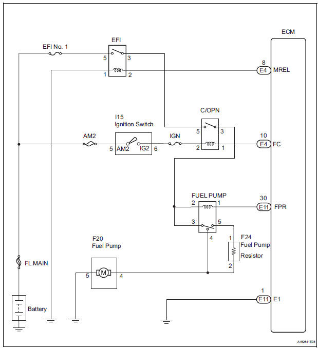
This troubleshooting procedure is based on the premise that the engine is started. If the engine is not started, proceed to the problem symptoms table (See page ES-27).
INSPECTION PROCEDURE
1 PERFORM ACTIVE TEST BY INTELLIGENT TESTER
(a) Connect the intelligent tester to the DLC3.
(b) Turn the ignition switch to the ON position and turn the intelligent tester ON.
(c) Enter the following menus: DIAGNOSIS / ENHANCED OBD II / ACTIVE TEST / FUEL PUMP SP CTL.
(d) Check the operation of the relay while operating it using the intelligent tester.
OK: Operating noise can be heard from the relay.


2 INSPECT RELAY (FUEL PUMP RELAY)
(a) Remove the FUEL PUMP relay from the engine room junction block.
(b) Measure the resistance according to the value(s) in the table below.
Standard resistance 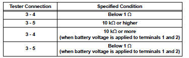
(c) Reinstall the FUEL PUMP relay.

3 CHECK HARNESS AND CONNECTOR (FUEL PUMP RELAY - ECM)
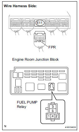
(a) Remove the FUEL PUMP relay from the engine room junction block.
(b) Disconnect the E11 ECM connector.
(c) Measure the resistance according to the value(s) in the table below.
Standard resistance 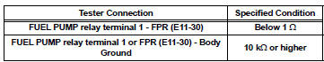
(d) Reconnect the ECM connector.
(e) Reinstall the FUEL PUMP relay

REPLACE ECM (See page ES-498)
 System Too
DESCRIPTION
The fuel trim is related to the feedback compensation value, not to the basic
injection time. The fuel trim
consists of both the short-term and long-term fuel trims.
The short-ter ...
 Random / Multiple Cylinder Misfire Detected
DESCRIPTION
When the engine misfires, high concentrations of hydrocarbons (HC) enter the
exhaust gas. High HC
concentration levels can cause increase in exhaust emission levels. Extremely ...
Other materials:
Precaution
1. Check that the battery cables are connected to the
correct terminals.
2. Disconnect the battery cables when the battery is
given a quick charge.
3. Do not perform tests with a high voltage insulation
resistance tester.
4. Never disconnect the battery cables while the engine
is runnin ...
Speaking on the phone
The following screen is displayed when speaking on the phone.
To adjust the call volume
Select “-” or “+”. You can also adjust the volume using the steering
switches or the volume knob.
To prevent the other party from hearing your voice
Select “Mute”.
Inputting tones
When usin ...
Half Connection in Center Airbag Sensor
Assembly Connectors
DTC B1135/24 Half Connection in Center Airbag Sensor
Assembly Connectors
DESCRIPTION
The center airbag sensor assembly connector has a mechanism that electrically
detects half connection.
The center airbag sensor assembly monitors the voltage applied to the
disconnection detection pins and ...
