Toyota Sienna Service Manual: Clearance Warning ECU Power Source Circuit
DESCRIPTION
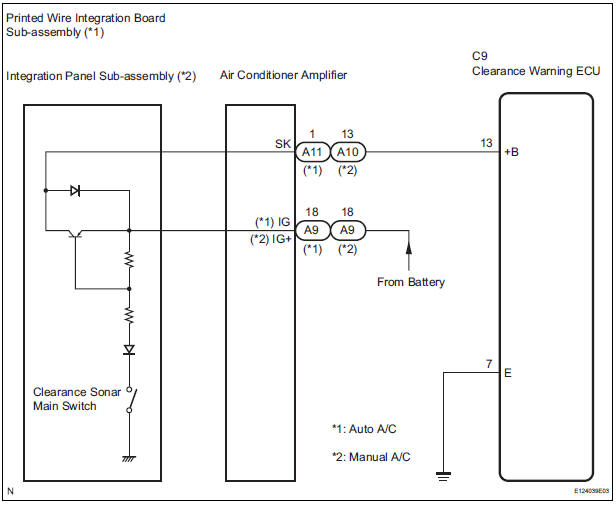
This circuit provides power to the clearance warning ECU.
WIRING DIAGRAM
INSPECTION PROCEDURE
1 CHECK HARNESS AND CONNECTOR (CLEARANCE WARNING ECU - AIR CONDITIONER AMPLIFIER)
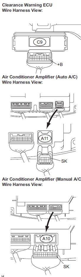
- Disconnect the connectors from the clearance warning ECU C9 and air conditioner amplifier connector A10 or A11.
- Measure the resistance according to the value(s) in the table below.
Standard resistance
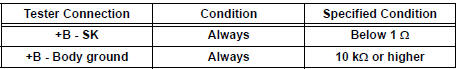
2 CHECK HARNESS AND CONNECTOR (CLEARANCE WARNING ECU - BODY GROUND)
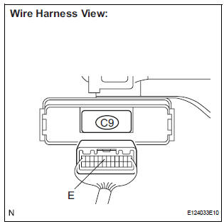
- Measure the resistance according to the value(s) in the table below.
Standard resistance
3 INSPECT CLEARANCE WARNING ECU
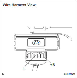
- Disconnect the clearance warning ECU connector.
- Turn the ignition switch ON.
- Turn the clearance sonar main switch ON.
- Measure the voltage between terminals +B and E of the ECU.
Standard voltage: 10 to 14 V
Result
PROCEED TO NEXT CIRCUIT INSPECTION SHOWN IN PROBLEM SYMPTOMS TABLE
4 INSPECT PRINTED WIRE INTEGRATION BOARD SUB-ASSEMBLY
- Check that the malfunction disappears when a known good printed wire integration board sub-assembly is installed.
OK: Malfunction disappears
REPLACE PRINTED WIRE INTEGRATION BOARD SUB-ASSEMBLY
5 INSPECT INTEGRATION PANEL SUB-ASSEMBLY
- Check that the malfunction disappears when a known good integration panel sub-assembly is installed.
OK: Malfunction disappears.
REPLACE INTEGRATION PANEL SUB-ASSEMBLY
 No. 1 Clearance Warning Buzzer Circuit
DESCRIPTION
The clearance warning ECU receives the ultrasonic sensor signal to sound the
front warning buzzer.
WIRING DIAGRAM
INSPECTION PROCEDURE
1 INSPECT FRONT BUZZER
Remove the c ...
 No. 2 Clearance Warning Buzzer Circuit
DESCRIPTION
The clearance warning ECU receives the ultrasonic sensor signal to sound the
rear warning buzzer.
WIRING DIAGRAM
INSPECTION PROCEDURE
1 CHECK HARNESS AND CONNECTOR (CLEARANCE WAR ...
Other materials:
ABS Warning Light does not Come ON
WIRING DIAGRAM
See page BC-47.
INSPECTION PROCEDURE
1 INSPECT ABS WARNING LIGHT
(a) Disconnect the skid control ECU connector.
(b) Turn the ignition switch to the ON position.
(c) Check that the ABS warning light comes on.
OK:
ABS warning light comes on.
HINT:
If troubleshooting has be ...
Multiplex Communication Circuit
DESCRIPTION
INSPECTION PROCEDURE
1 GO TO CAN COMMUNICATION SYSTEM
(a) Refer to the CAN communication system (See page CA-
7).
(b) If the CAN communication system is operating normally,
proceed to the next step.
2 GO TO MULTIPLEX COMMUNICATION SYSTEM (BEAN)
(a) Refer to the multiplex com ...
Positioning a floor jack
When using a floor jack, follow the instructions in the manual
provided with the jack and perform the operation safely.
When raising your vehicle with a floor jack, position the jack correctly.
Improper placement may damage your vehicle or cause
injury.
Front
Rear
2WD ...
