Toyota Sienna Service Manual: Open in Pump Motor Circuit
DTC C1251/51 Open in Pump Motor Circuit
DESCRIPTION
The motor relay (semiconductor relay) is housed in the brake actuator assembly and drives the pump motor based on a signal from the skid control ECU.

WIRING DIAGRAM
Refer to DTCs C0273/13 and C0274/14 (See page BC-31).
INSPECTION PROCEDURE
HINT: After step 1 is complete, start the inspection from step 2 when using the intelligent tester, and from step 3 when not using the intelligent tester.
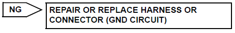
1 INSPECT SKID CONTROL ECU (GND TERMINAL CONTINUITY)
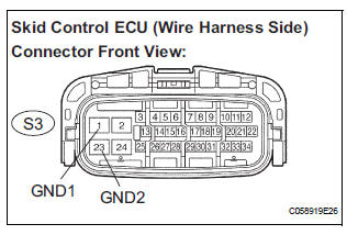
(a) Disconnect the skid control ECU connector.
(b) Measure the resistance according to the value(s) in the table below.
Standard resistance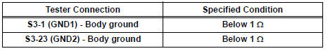

2 PERFORM ACTIVE TEST BY INTELLIGENT TESTER (ABS MOTOR RELAY)
(a) Reconnect the skid control ECU connector.
(b) Connect the intelligent tester to the DLC3.
(c) Turn the ignition switch to the ON position and turn the intelligent tester main switch on.
(d) Start the engine.
(e) Select the ACTIVE TEST mode on the intelligent tester.
ABS: 
(f) Check operating sound of the ABS motor when operating it with the intelligent tester.
OK: The operating sound of the ABS motor is heard.


3 RECONFIRM DTC
(a) Clear the DTCs (See page BC-10).
(b) Start the engine.
(c) Drive the vehicle at the speed of 6 km/h (4 mph) or more.
(d) Check that the same DTC is recorded (See page BC- 10).
HINT:
- Reinstall the sensors, connectors, etc. and restore the vehicle to its prior condition before rechecking for DTCs.
- If a speed signal of 6 km/h (4 mph) or more is input to the skid control ECU, with the ignition switch on and the stop light switch off, the ECU performs selfdiagnosis of the motor and solenoid circuits.
Result 
HINT:
- If any DTCs are output while jiggling a connector or wire harness of the brake actuator (skid control ECU), inspect and repair the connector or wire harness.
- If the normal system code is output, slightly jiggle the connectors, wire harnesses, and fuses of the brake actuator assembly. Make sure that no DTCs are output.
- These DTCs may be stored due to a malfunction in the connector terminal connection, etc.


REPLACE BRAKE ACTUATOR ASSEMBLY
 Open in Stop Light Switch Circuit
DTC C1249/49 Open in Stop Light Switch Circuit
DESCRIPTION
This skid control ECU inputs the stop light switch signal and detects the
status of brake operation.
The skid control ECU has an open ...
 ABS Warning Light Remains ON
DESCRIPTION
If any of the following is detected, the ABS warning light remains on.
The skid control ECU connectors are disconnected from the skid control
ECU.
There is a malfunction in the s ...
Other materials:
Mute Signal Circuit between Radio and Navigation Assembly and
Television Display Assembly
DESCRIPTION
The radio and navigation assembly controls the volume according to the MUTE
signal from the television
display assembly.
The MUTE signal is sent to reduce noise and a popping sound generated when
switching the mode, etc.
If there is an open in the circuit, noise can be heard ...
Short to GND in Front Passenger Side Squib
Circuit
DTC B0107/51 Short to GND in Front Passenger Side Squib
Circuit
DESCRIPTION
The front passenger side squib circuit consists of the center airbag sensor
assembly and the front
passenger airbag assembly.
The circuit instructs the SRS to deploy when deployment conditions are met.
DTC B0107/ ...
Power easy access system
The seat is automatically adjusted to allow the driver to enter and exit
the vehicle easily.
When all of the following have
been performed, the driver’s seat
is automatically adjusted to a
position that allows driver to enter
and exit the vehicle easily.
The shift lever has been sh ...
