Toyota Sienna Service Manual: Evaporative Emission Control System Incorrect Purge Flow
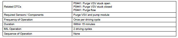
DTC SUMMARY
DESCRIPTION
The circuit description can be found in the EVAP (Evaporative Emission) System (See page ES-409).
INSPECTION PROCEDURE
Refer to the EVAP System (See page ES-412).
MONITOR DESCRIPTION
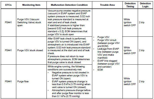
The two monitors, Key-Off and Purge Flow, are used to detect malfunctions relating to DTC P0441. The Key-off monitor is initiated by the ECM internal timer, known as the soak timer, 5 hours*1 after the ignition switch is turned off. The purge flow monitor runs while the engine is running.
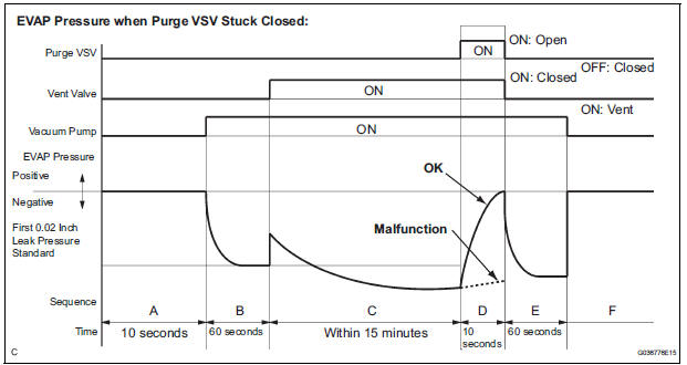
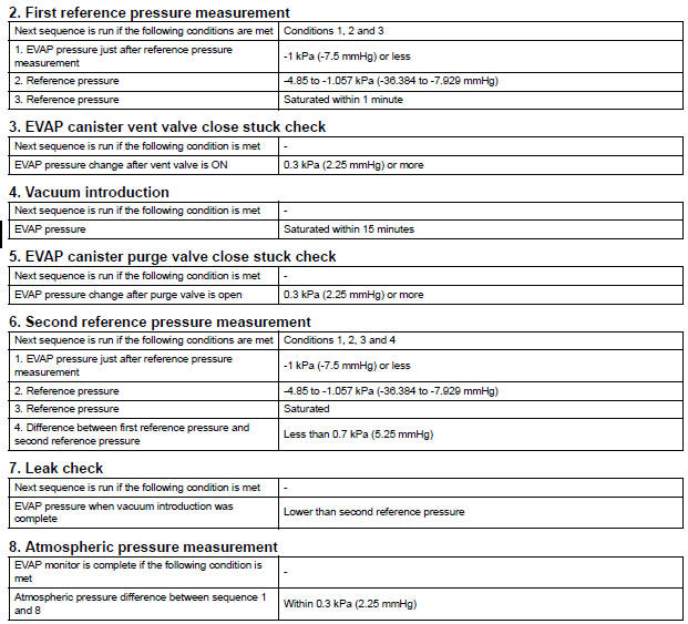
1. KEY-OFF MONITOR
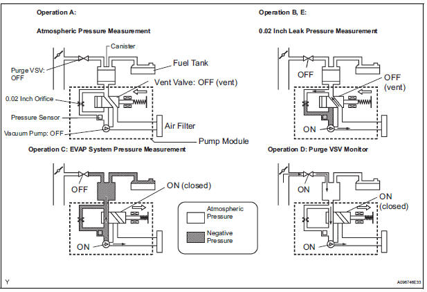
5 hours*1 after the ignition switch is turned off, the electric vacuum pump creates negative pressure (vacuum) in the EVAP (Evaporative Emission) system. The ECM monitors for leaks and actuator malfunctions based on the EVAP pressure.
HINT:
*1: If the engine coolant temperature is not below 35°C (95°F) 5 hours after the ignition switch is turned off, the monitor check starts 2 hours later. If it is still not below 35°C (95°F) 7 hours after the ignition switch is turned off, the monitor check starts 2.5 hours later.
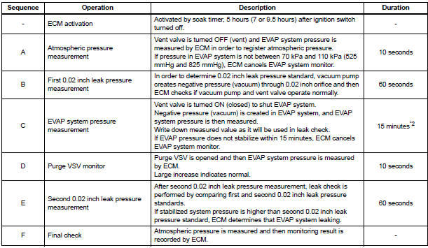
*2: If only a small amount of fuel is in the fuel tank, it takes longer for the EVAP pressure to stabilize.
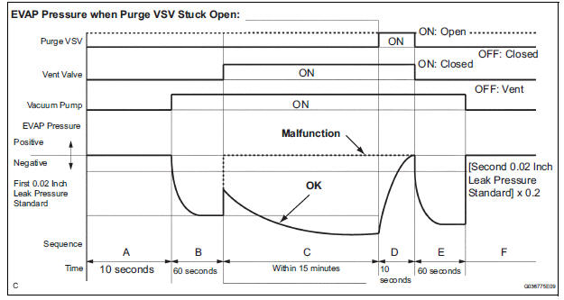
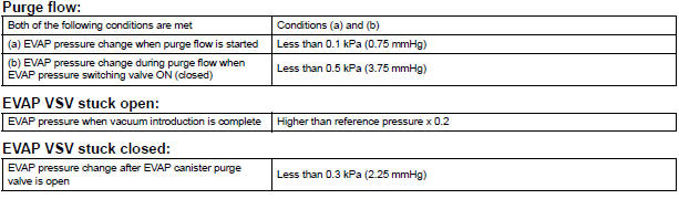
(a) Purge VSV stuck open
In operation C, the vacuum pump creates negative pressure (vacuum) in the EVAP (Evaporative Emission) system. The EVAP system pressure is then measured by the ECM using the pressure sensor. If the stabilized system pressure is higher than [second 0.02 inch leak pressure standard x 0.2], the ECM interprets this as the purge VSV (Vacuum Switching Valve) being stuck open.
The ECM illuminates the MIL and sets the DTC (2 trip detection logic).
(b) Purge VSV stuck closed
In operation D, the pressure sensor measures the EVAP (Evaporative Emission) system pressure. The pressure measurement for purge VSV monitor is begun when the purge VSV is turned on (open) after the EVAP leak check. When the measured pressure indicates an increase of 0.3 kPa (2.25 mmHg) or more, the purge VSV is functioning normally. If the pressure does not increase, the ECM interprets this as the purge VSV being stuck closed. The ECM illuminates the MIL and sets the DTC (2 trip detection logic).
2. PURGE FLOW MONITOR
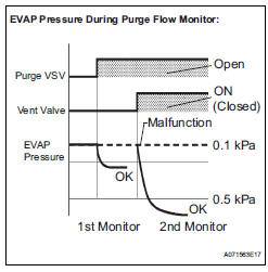
The purge flow monitor consists of the two step monitors.
The 1st monitor is conducted every time and the 2nd monitor is activated if necessary.
- The 1st monitor
While the engine is running and the purge VSV (Vacuum Switching Valve) is on (open), the ECM monitors the purge flow by measuring the EVAP pressure change. If negative pressure is not created, the ECM begins the 2nd monitor.
- The 2nd monitor
The vent valve is turned on (closed) and the EVAP pressure is then measured. If the variation in the pressure is less than 0.5 kPa (3.75 mmHg), the ECM interprets this as the purge VSV being stuck closed, and illuminates the MIL and sets DTC P0441 (2 trip detection logic).
Atmospheric pressure check: In order to ensure reliable malfunction detection, the variation between the atmospheric pressures, before and after conduction of the purge flow monitor, is measured by the ECM.
MONITOR STRATEGY
TYPICAL ENABLING CONDITIONS
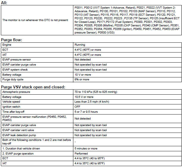
Key-off monitor sequence 1 to 8

TYPICAL MALFUNCTION THRESHOLDS
MONITOR RESULT
Refer to CHECKING MONITOR STATUS (See page ES-19).
DTC SUMMARY
HINT:
The canister pressure sensor is built into the canister pump module.
DESCRIPTION
The description can be found in the EVAP (Evaporative Emission) System (See page ES-409).
MONITOR DESCRIPTION
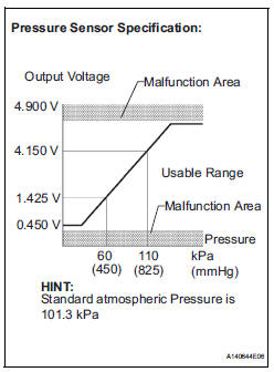
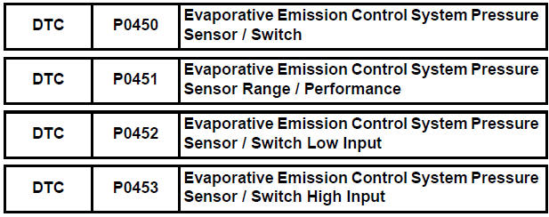
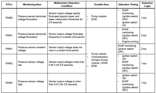
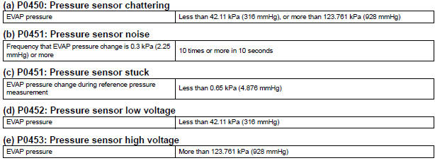
1. DTC P0450: Pressure sensor abnormal voltage fluctuation
If the pressure sensor voltage output rapidly fluctuates between less than 0.45 V and more than 4.9 V, the ECM interprets this as an open or short circuit malfunction in the pressure sensor or its circuit, and stops the EVAP (Evaporative Emission) system monitor. The ECM then illuminates the MIL and sets the DTC (1 trip detection logic).
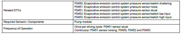
2. DTC P0451: Pressure sensor abnormal voltage fluctuation or being constant
If the pressure sensor voltage output fluctuates rapidly for 10 seconds, the ECM stops the EVAP system monitor. The ECM interprets this as the pressure sensor voltage fluctuating, and stops the EVAP system monitor. The ECM then illuminates the MIL and sets the DTC.
Alternatively, if the sensor voltage output does not change for 10 seconds, the ECM interprets this as the sensor being stuck, and stops the monitor. The ECM then illuminates the MIL and sets the DTC.
(Both the malfunctions are detected by 2 trip detection logic.)
3. DTC P0452: Pressure sensor voltage low
If the pressure sensor voltage output is below 0.45 V, the ECM interprets this as an open or short circuit malfunction in the pressure sensor or its circuit, and stops the EVAP system monitor. The ECM then illuminates the MIL and sets the DTC (1 trip detection logic).
4. DTC P0453: Pressure sensor voltage high
If the pressure sensor voltage output is 4.9 V or more, the ECM interprets this as an open or short circuit malfunction in the pressure sensor or its circuit, and stops the EVAP system monitor. The ECM then illuminates the MIL and sets the DTC (1 trip detection logic).
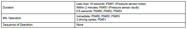
MONITOR STRATEGY
TYPICAL ENABLING CONDITIONS
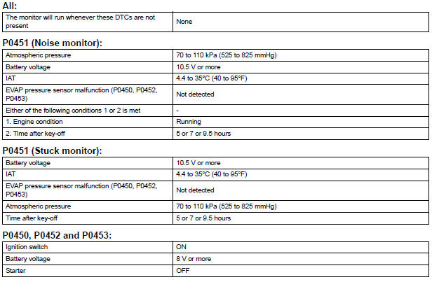
TYPICAL MALFUNCTION THRESHOLDS
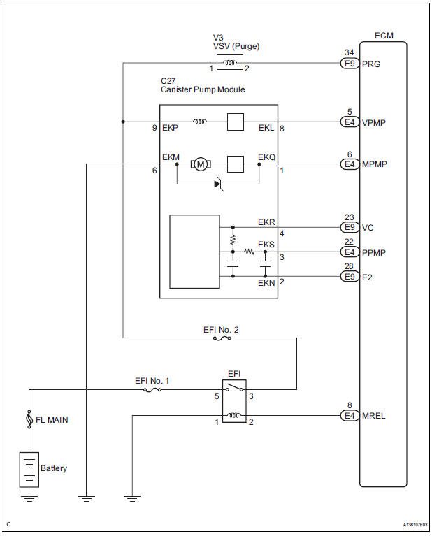
WIRING DIAGRAM
INSPECTION PROCEDURE
NOTICE:
|
1 CONFIRM DTC AND EVAP PRESSURE
(a) Connect the intelligent tester to the DLC3.
(b) Turn the ignition switch to the ON position (do not start the engine).
(c) Turn the tester on.
(d) Select the following menu items: DIAGNOSIS / ENHANCED OBD II / DTC INFO / CURRENT CODES.
(e) Read DTCs.
(f) Select the following menu items: DIAGNOSIS / ENHANCED OBD II / DATA LIST / EVAP / EVAP VAPOR PRESS.
(g) Read the EVAP (Evaporative Emission) pressure displayed on the tester.
Result 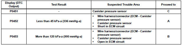


2 CHECK HARNESS AND CONNECTOR (CANISTER PUMP MODULE - ECM)
(a) Turn the ignition switch off.
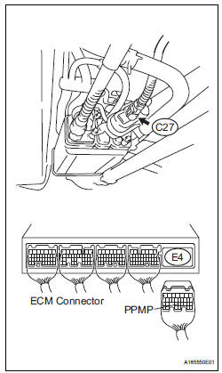
(b) Disconnect the E4 ECM connector.
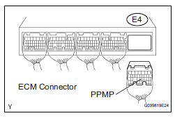
(c) Measure the resistance between the PPMP terminal of the ECM connector and the body ground.
Result 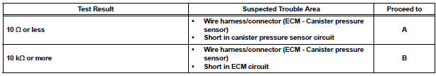
(d) Reconnect the ECM connector.


3 CHECK HARNESS AND CONNECTOR (CANISTER PUMP MODULE - ECM)
(a) Disconnect the C27 canister pump module connector.
(b) Disconnect the E4 ECM connector.
(c) Measure the resistance between the PPMP terminal of the ECM connector and the body ground.
Result 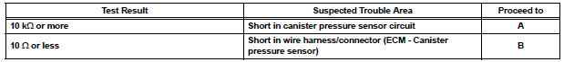
(d) Reconnect the canister pump module connector.
(e) Reconnect the ECM connector.


4 CHECK HARNESS AND CONNECTOR (CANISTER PUMP MODULE - ECM)
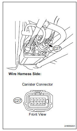
(a) Disconnect the C27 canister pump module connector.
(b) Turn the ignition switch to the ON position.
(c) Measure the voltage and resistance of the canister connector.
Standard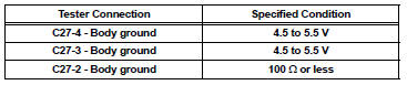
Result 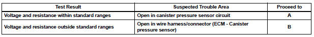
(d) Reconnect the canister pump module connector.

5 REPLACE CHARCOAL CANISTER ASSEMBLY
(a) Replace the canister assembly (See page EC-8).
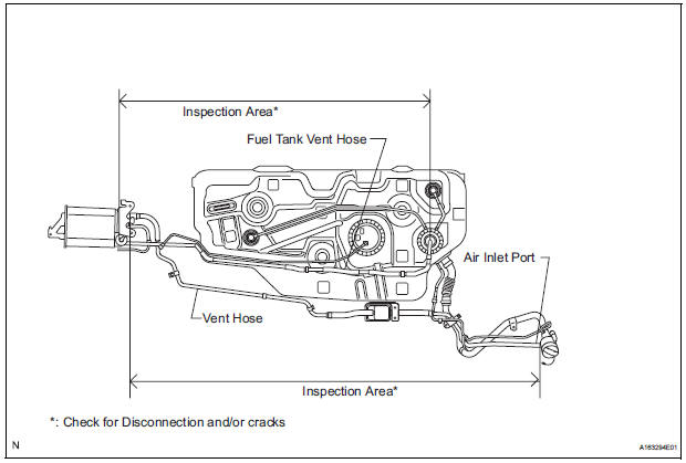
| NOTICE: When replacing the canister, check the canister pump module interior and related pipes for water, fuel and other liquids. If liquids are present, check for disconnections and/or cracks in the following: 1) the pipe from the air inlet port to the canister pump module; 2) the canister filter; and 3) the fuel tank vent hose. |

6 REPAIR OR REPLACE HARNESS OR CONNECTOR (CANISTER PUMP MODULE - ECM)
HINT:
If the exhaust tailpipe has been removed, go to the next step before reinstalling it.

7 REPLACE ECM
(a) Replace the ECM (See page ES-498).

8 CHECK WHETHER DTC OUTPUT RECURS (AFTER REPAIR)
(a) Connect the intelligent tester to the DLC3.
(b) Turn the ignition switch to the ON position and turn the tester on.
(c) Wait for at least 60 seconds.
(d) On the tester, select the following menu items: DIAGNOSIS / ENHANCED OBD II / DTC INFO / PENDING CODES.
HINT:
If no pending DTCs are displayed on the tester, the repair has been successfully completed.

COMPLETED
 Evaporative Emission System Reference Orifice
DTC SUMMARY
HINT:
The 0.02 inch orifice is located inside the pump module.
DESCRIPTION
The circuit description can be found in the EVAP (Evaporative Emission)
System (See page ES-409).
...
 Evaporative Emission Control System Leak Detected
DTC SUMMARY
DESCRIPTION
The circuit description can be found in the EVAP (Evaporative Emission)
System (See page ES-409).
INSPECTION PROCEDURE
Refer to the EVAP System (See page ES-412).
...
Other materials:
Installation
HINT:
Install the RH side by the same procedure as the LH side.
1. INSTALL FRONT DISC BRAKE CYLINDER SLIDE BUSH
(a) Apply the lithium soap base glycol grease to a new
front disc brake cylinder slide bush.
(b) Install the cylinder slide bush to the bottom side of
the front disc brake cyli ...
Power Slide Door does not Fully Open
DESCRIPTION
When the LH / RH rear window is open 105 mm (5.91 in.) or more,
the slide door half-open stopper is
activated to force the slide door to stop at approximately 105 mm (5.91 in.)
from the fully open position.
This is caused by the jam protection function between the sli ...
Installation
1. INSTALL HEATED OXYGEN SENSOR (for Bank 2
Sensor 2)
(a) Using SST, install the heated oxygen sensor to the
front exhaust pipe.
SST 09224-00010
Torque: 40 N*m (408 kgf*cm, 30 ft.*lbf) for use
with SST
44 N*m (449 kgf*cm, 32 ft.*lbf) for use
without SST
HINT:
Use a torque wrench wit ...
