Toyota Sienna Service Manual: Radio and Navigation Assembly Power Source Circuit
DESCRIPTION
This is the power source circuit to operate the radio and navigation assembly.
WIRING DIAGRAM
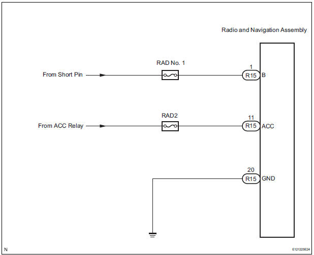
INSPECTION PROCEDURE
1 INSPECT RADIO AND NAVIGATION ASSEMBLY
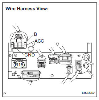
- Disconnect the radio and navigation assembly connector R15.
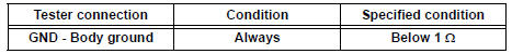
- Measure the resistance according to the value(s) in the table below.
Standard resistance
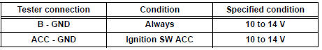
- Measure the voltage according to the value(s) in the table below.
Standard voltage
PROCEED TO NEXT CIRCUIT INSPECTION SHOWN IN PROBLEM SYMPTOMS TABLE
 Stereo Component Amplifier Power Source Circuit
DESCRIPTION
This circuit provides power to the stereo component amplifier.
WIRING DIAGRAM
INSPECTION PROCEDURE
1 INSPECT STEREO COMPONENT AMPLIFIER
Disconnect the stereo component ampl ...
 Television Display Power Source Circuit
DESCRIPTION
This is the power source circuit to operate the television display assembly.
WIRING DIAGRAM
INSPECTION PROCEDURE
1 INSPECT TELEVISION DISPLAY ASSEMBLY
Disconnect the connec ...
Other materials:
Brake Switch "A" Circuit
DTC P0571 Brake Switch "A" Circuit
DESCRIPTION
When the brake pedal is depressed, the stop light switch sends a signal to
the ECM. When the ECM
receives this signal, it cancels the cruise control. The fail-safe function
operates to enable normal driving
even if there is a malfuncti ...
Сamshaft timing oil control valve assembly
COMPONENTS
ON-VEHICLE INSPECTION
1. INSPECT CAMSHAFT TIMING CONTROL VALVE ASSEMBLY
(a) Connect the intelligent tester to the DLC3.
(b) Turn the ignition switch to the ON position.
(c) Start the engine and warm it up.
(d) Select the intelligent tester from the ACTIVE TEST
...
GPS Receiver Error
DTC 58-11 GPS Receiver Error
DTC 80-11 GPS Receiver Error
DESCRIPTION
DTC No.
DTC Detection Condition
Trouble Area
58-11
RTC, ROM, and RAM of the GPS receiver and
TCXO error
GPS receiver is failed
Radio and navigation assembly ...
