Toyota Sienna Service Manual: Radio Receiver Communication Error
INSPECTION PROCEDURE
1 IDENTIFY THE COMPONENT SHOWN BY THE SUB-CODE
- Enter the diagnostic mode
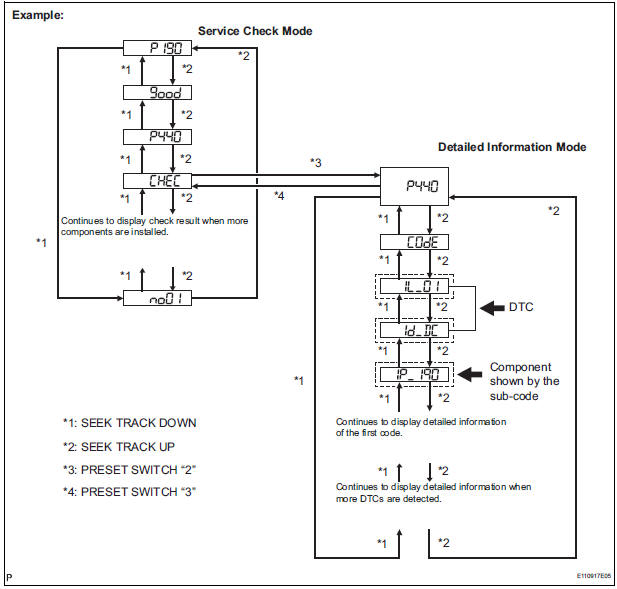
- Press the preset switch "3" to change to "Detailed Information Mode".
- Identify the component shown by the sub-code.
HINT:
- "190 (radio receiver)" is the component shown by the subcode in the example shown in the illustration.
- For details of the DTC display, refer to "DTC CHECK/ CLEAR"
2 CHECK POWER SOURCE CIRCUIT OF COMPONENT SHOWN BY SUB-CODE
- Inspect the power source circuit of the component shown
by the sub-code.
If the power source circuit is operating normally, proceed to the next step.
Component Table:
|
Component |
Proceed to |
| Stereo component amplifier (440) | Stereo component amplifier power source circuit |
| Television display assembly (1B0) | Television display assembly power source circuit |
3 INSPECT RADIO RECEIVER
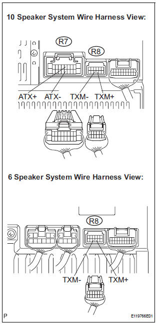
- Disconnect the radio receiver connectors.
- Measure the resistance according to the value(s) in the table below.
Standard resistance
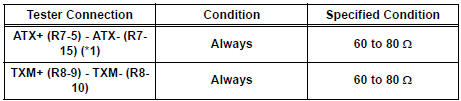
*1: 10 Speaker System
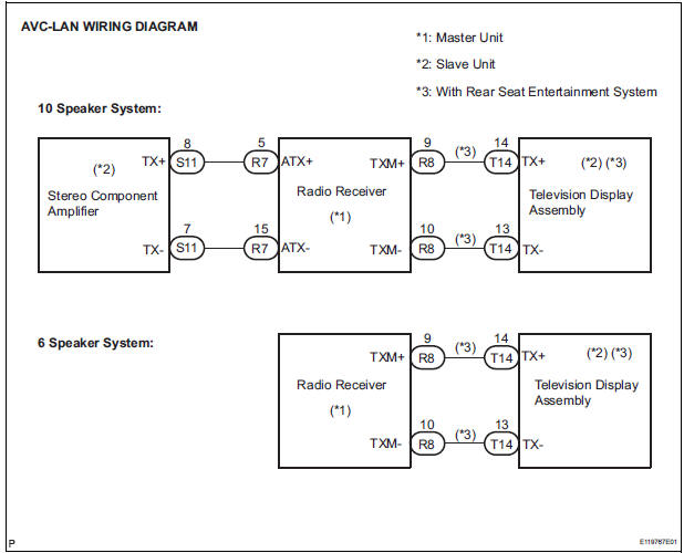
4 CHECK HARNESS AND CONNECTOR (RADIO RECEIVER - COMPONENT SHOWN BY SUB-CODE)
HINT:
- Start the check from the circuit that is near the component shown by the sub-code first.
- For details of the connectors, refer to the "TERMINALS OF ECU".
- Referring to the AVC-LAN wiring diagram below, check the AVC-LAN circuit between the radio receiver and the component shown by the sub-code.
- Disconnect all connectors between the radio receiver and the component shown by sub-code.
- Check for an open or short in the AVC-LAN circuit between the radio receiver and the component shown by the sub-code.
OK: There is no open or short circuit.
5 REPLACE COMPONENT SHOWN BY SUB-CODE
- Replace the component shown by the sub-code with a normal one and check if the same problem occurs again.
OK: Same problem does not occur.
END
 Vehicle Speed Signal Circuit between Stereo Component Amplifier and
Combination Meter
Vehicle Speed Signal Circuit between Stereo Component Amplifier and
Combination Meter
DESCRIPTION
This circuit is necessary for the ASL (Auto Sound Leveliser) built into the
stereo component amplifier.
Speed signals are received from the combination meter and used for the ASL.
...
 Stereo Component Amplifier Communication Error
INSPECTION PROCEDURE
1 IDENTIFY THE COMPONENT SHOWN BY THE SUB-CODE
Enter the diagnostic mode.
Press the preset switch "3" to change to "Detailed
Information Mode" ...
Other materials:
Control Module Performance
DESCRIPTION
The ECM continuously monitors its main and sub CPUs. This self-check ensures
that the ECM is
functioning properly. If outputs from the CPUs are different and deviate from
the standards, the ECM will
illuminate the MIL and set a DTC immediately.
The ECM also monitors the cru ...
Lumbar support adjuster assembly
INSPECTION
1. INSPECT LUMBAR SUPPORT ADJUSTER ASSEMBLY
Check operation of the lumbar support adjuster
motor.
Check if the lumbar support adjuster moves
smoothly when the battery is connected to the
lumbar support adjuster motor connector
terminal.
OK
If the r ...
Installation
1. INSTALL NO. 2 REAR SEAT OUTER BELT ASSEMBLY
NOTICE:
Do not disassemble the retractor.
Check the degree of tilt when the No. 2 rear seat
outer belt assembly begins to lock the ELR.
Check that the belt does not lock within 15 of
tilt in all directions but that the be ...
