Toyota Sienna Service Manual: Removal
1. Remove windshield wiper motor assembly hint: (see page ww-4) 2. Remove front outer cowl top panel subassembly (see page em-27) 3. Drain engine coolant (see page co-6) 4. Remove v-bank cover sub-assembly (see page em-28) 5. Remove no. 2 Air cleaner inlet (see page em- 28) 6. Remove no. 1 Air cleaner inlet (see page em- 28) 7. Remove air cleaner cap sub-assembly
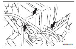
(A) disconnect the 3 vacuum hoses.
(b) Remove the No. 2 ventilation hose and air cleaner hose band.
(c) Disconnect the vacuum hose (EVAP) from the air cleaner hose.
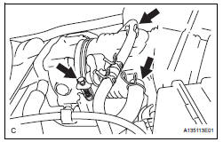
(d) Disconnect the mass air flow meter connector.
(e) Remove the 2 bolts and air cleaner cap subassembly.
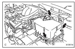
8. REMOVE AIR CLEANER CASE SUB-ASSEMBLY (See page EM-28)
9. REMOVE THROTTLE BODY
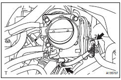
(a) Disconnect the throttle body connector and clamp.
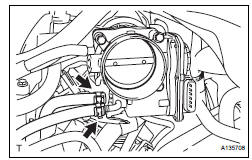
(b) Disconnect the 2 water by-pass hoses from the throttle body.
(c) Remove the 4 bolts and throttle body.
(d) Remove the throttle body gasket from the intake air surge tank.
INSPECTION
1. INSPECT THROTTLE BODY
(a) Using an ohmmeter, measure the resistance between the terminals.
Standard resistance
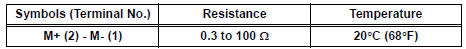
If the result is not as specified, replace the throttle body assembly.
 On-vehicle inspection
1. INSPECT THROTTLE BODY
(a) Listen to the throttle control motor operating sounds.
(1) Turn the ignition switch to the ON position.
(2) When pressing the accelerator pedal position
sensor lever ...
 Installation
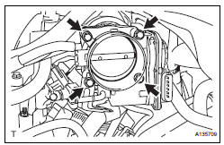
1. INSTALL THROTTLE BODY
(a) Install a new throttle body gasket to the intake air
surge tank.
(b) Install the throttle body with the 4 bolts.
Torque: 10 N*m (102 kgf*cm, 7 ft.*lbf)
...
Other materials:
How to proceed with
troubleshooting
HINT:
Troubleshoot in accordance with the procedures on the
following pages.
1 VEHICLE BROUGHT TO WORKSHOP
2 CUSTOMER PROBLEM ANALYSIS CHECK AND SYMPTOM CHECK
3 PROBLEM SYMPTOMS TABLE
When problem is not listed on problem symptoms table,
proceed to A.
When problem is listed on pro ...
TC and CG Terminal Circuit
DESCRIPTION
Connecting terminals TC and CG of the DLC3 causes the system to enter the
self-diagnostic mode. If a
malfunction is present, DTCs will be output.
HINT:
When a particular warning light remains blinking, a ground short in the wiring
of terminal TC of the DLC3
or an internal ground ...
Short in CAN Bus Lines
DESCRIPTION
The CAN bus wires are considered to be shorted when the resistance between
terminals 6 (CANH) and
14 (CANL) of the DLC3 is below 54 Ω.
Symptom
Trouble Area
Resistance between terminals 6 (CANH) and 14 (CANL) of the DLC3
is below 54 Ω.
...
