Toyota Sienna Service Manual: Reverse Signal Circuit
DESCRIPTION
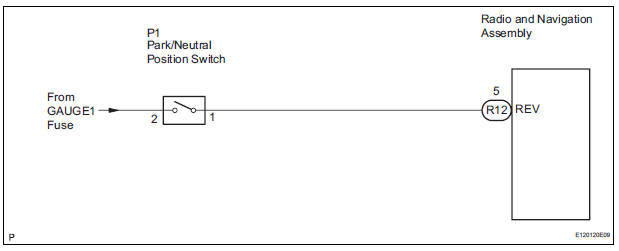
The radio and navigation assembly receives a reverse signal from the park/neutral position switch and information about the GPS antenna, and then adjusts vehicle position.
WIRING DIAGRAM
INSPECTION PROCEDURE
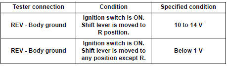
1 INSPECT RADIO AND NAVIGATION ASSEMBLY

- Disconnect the radio and navigation assembly connector R12.
- Measure the voltage according to the value(s) in the table below.
Standard voltage
2 CHECK HARNESS AND CONNECTOR (RADIO AND NAVIGATION - PARK / NEUTRAL POSITION SWITCH)
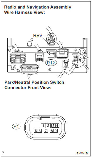
- Disconnect the radio and navigation assembly connector R12 and park/neutral position switch connector P1.
- Measure the resistance according to the value(s) in the table below.
Standard resistance
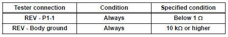
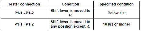
3 INSPECT PARK / NEUTRAL POSITION SWITCH

- Disconnect the park/neutral position switch connector P1.
- Measure the resistance according to the value(s) in the table below.
Standard resistance
REPAIR OR REPLACE HARNESS OR CONNECTOR
 AVC-LAN Circuit
DESCRIPTION
Each unit of the navigation system connected to the AVC-LAN (communication
bus) transfers the signal of
each switch by communication.
When a short to +B or short to ground occurs in ...
 Navigation Voice Circuit
DESCRIPTION
This circuit is used when the voice guidance in the navigation system is on.
WIRING DIAGRAM
INSPECTION PROCEDURE
1 CHECK HARNESS AND CONNECTOR (RADIO AND NAVIGATION ASSEMBLY - STER ...
Other materials:
Problem symptoms table
Before inspecting the suspected areas listed in the table
below, check the fuse and relay.
Before inspecting the suspected areas listed in the table
below, check the DTCs.
Methods used to verify the cause of the problem are listed
in order of probability in the suspected are ...
Selecting trailer ball
Use the correct trailer ball for your application.
Trailer ball load rating
Matches or exceeds the gross
trailer weight rating of the trailer.
Ball diameter
Matches the size of the trailer coupler.
Most couplers are stamped
with the required trailer ball size.
Shank len ...
Display Signal Circuit between Video Terminal and Television Display
DESCRIPTION
This is the display signal circuit from the video terminal to the television
display assembly.
WIRING DIAGRAM
INSPECTION PROCEDURE
1 CHECK HARNESS AND CONNECTOR (TELEVISION DISPLAY ASSEMBLY - VIDEO
TERMINAL)
Disconnect the connectors from the video terminal and
tele ...
