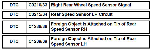
Toyota Sienna Service Manual: Right Rear Wheel Speed Sensor Signal
DESCRIPTION
Refer to DTCs C0200/31, C0205/32, C1235/35 and C1236/36 (See page BC-92).
HINT:
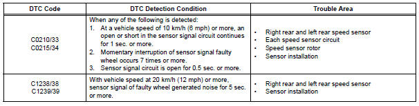
- DTC C0210/33 and C1238/38 are for the right rear speed sensor.
- DTC C0215/34 and C1239/39 are for the left rear speed sensor.
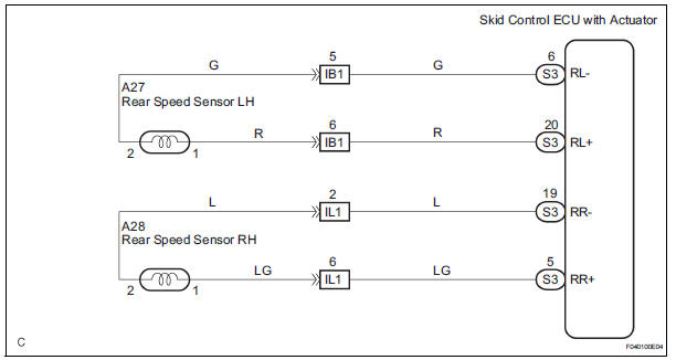
WIRING DIAGRAM
INSPECTION PROCEDURE
1 READ VALUE ON INTELLIGENT TESTER (REAR SPEED SENSOR)
(a) Connect the intelligent tester to the DLC3.
(b) Start the engine.
(c) Select the DATA LIST mode on the intelligent tester.
ABS / VSC: 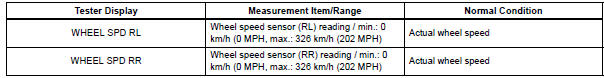
(d) Check that there is no difference between the speed value output from the speed sensor displayed by the intelligent tester and the speed value displayed on the speedometer when driving the vehicle
OK: There is almost no difference in the displayed speed value.
HINT: There is tolerance of +- 10 % in the speedometer indication.

2 CHECK SPEED SENSOR AND SENSOR ROTOR SERRATIONS
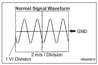
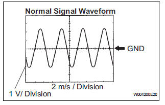
(a) INSPECTION USING OSCILLOSCOPE:
(1) Connect the oscilloscope to terminals RR+ - RR- or RL+ - RL- of the skid control ECU.
(2) Drive the vehicle at approximately 19 mph (30 km/ h), and check the signal waveform.
OK: A waveform as shown in a figure should be output.
HINT:
- As vehicle speed (wheel revolution speed) in creases, a cycle of the waveform narrows and the fluctuation in the output voltage becomes greater.
- hen noise is identified in the waveform on the oscilloscope, error signals are generated due to the speed sensor rotor's scratches, looseness or foreign matter attached to it.
NOTICE: When replacing the brake actuator assembly, perform zero point calibration (See page BC-70).


REPLACE BRAKE ACTUATOR ASSEMBLY
3 INSPECT REAR SPEED SENSOR
(a) 2WD
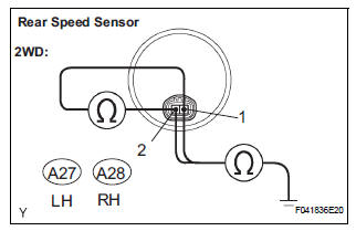
(1) Disconnect the skid control sensor connector.
(2) Measure the resistance according to the value(s) in the table below.
Standard resistance:
LH 
RH 
NOTICE: Check the speed sensor signal after replacement (See page BC-72).
(b) 4WD
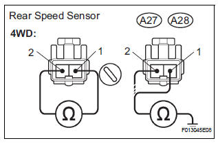
(1) Remove the seat cushion seatback.
(2) Disconnect the speed sensor connector.
(3) Measure the resistance according to the value(s) in the table below.
Standard resistance:
LH 
RH 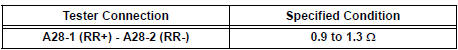
(4) Measure the resistance according to the value(s) in the table below
Standard resistance:
LH 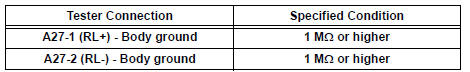
RH 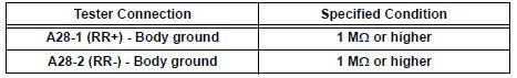
NOTICE: Check the speed sensor signal after the replacement. (See page BC-72)

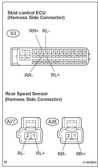
4 CHECK HARNESS AND CONNECTOR (REAR SPEED SENSOR - SKID CONTROL ECU)
(a) Disconnect the skid control ECU connector and the skid control sensor connector.
(b) Measure the resistance according to the value(s) in the table below.
Standard resistance:
LH 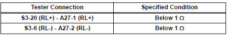
RH 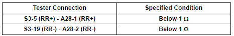
(c) Measure the resistance according to the value(s) in the table below.
Standard resistance:
LH 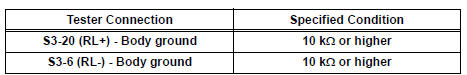
RH 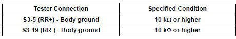

5 CHECK SPEED SENSOR AND SENSOR ROTOR SERRATIONS
(a) INSPECTION USING OSCILLOSCOPE
(1) Connect the oscilloscope to terminals RR+ - RR- or RL+ - RL- of the skid control ECU.
(2) Drive the vehicle at approximately 19 mph (30 km/ h), and check the signal waveform.
OK: A waveform as shown in a figure should be output.
HINT:
- As the vehicle speed (wheel revolution speed) increases, a cycle of the waveform narrows and the fluctuation in the output voltage becomes greater.
- When noise is identified in the waveform on the oscilloscope, error signals are generated due to the speed sensor rotor's scratches, looseness or foreign matter attached to it.
NOTICE: When replacing the brake actuator assembly, perform zero point calibration (See page BC-70).
REPLACE BRAKE ACTUATOR ASSEMBLY
6 CHECK REAR SPEED SENSOR INSTALLATION
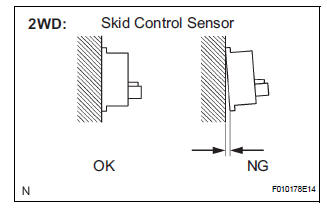
(a) 2WD
(1) Check the sensor installation.
OK: There is no clearance between the sensor and rear axle carrier.
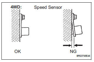
(b) 4WD
(1) Check the sensor installation.
OK: There is no clearance between the sensor and rear axle carrier.
The installation bolt is tightened properly.
Torque: 8.0 N*m (82 kgf*cm, 71 in.*lbf)
NOTICE: Check the speed sensor signal after the replacement (See page BC-72).

7 CHECK SPEED SENSOR ROTOR
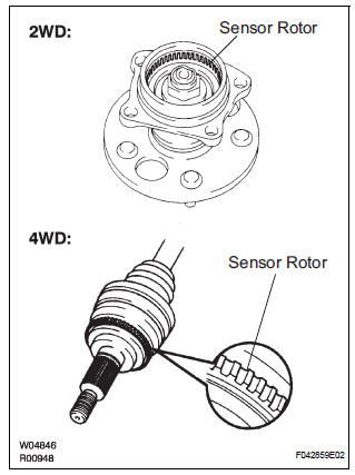
(a) Remove the rear axle hub and bearing, or rear drive shaft (See page AH-16 for 2WD, or DS-21 for 4WD).
(b) Check the sensor rotor serrations.
OK: No scratches, missing teeth or foreign objects.
Result 
NOTICE: Check the speed sensor signal after the replacement (See page BC-72).

8 CHECK REAR SPEED SENSOR TIP
(a) Remove the rear speed sensor (See page BC-190 for 2WD or BC-194 for 4WD).
(b) Check the sensor tip.
OK: No scratches or foreign matter on the sensor tip.
NOTICE:
- Check the speed sensor signal after the replacement (See page BC-72).
- When replacing the brake actuator assembly, perform zero point calibration (See page BC-70).

REPLACE BRAKE ACTUATOR ASSEMBLY
 Right Front Wheel Speed Sensor Signal
DESCRIPTION
The speed sensor detects wheel speed and sends the appropriate signals to the
ECU. These signals are
used to control the ABS control system. The front and rear rotors have 48
ser ...
 SFR Solenoid Circuit
DESCRIPTION
This solenoid goes on when signals are received from the ECU and controls the
pressure acting on the
wheel cylinders to control the braking force.
WIRING DIAGRAM
INSPECTI ...
Other materials:
Reassembly
1. INSTALL REAR DOOR WIRE SUB-ASSEMBLY LH
Install the wire.
NOTICE:
When installing the wire, push the areas where
the clips are installed in order to prevent
damage and deformation.
Install the 2 screws.
2. INSTALL REAR DOOR LOCK ASSEMBLY LH
Apply MP grease to the slidi ...
Throttle / Pedal Position Sensor
HINT:
These DTCs relate to the Accelerator Pedal Position (APP) sensor.
DESCRIPTION
HINT:
This ETCS (Electronic Throttle Control System) does not use a throttle cable.
The Accelerator Pedal Position (APP) sensor is integrated with the accelerator
pedal bracket and has 2
sensor circuits ...
Removal
1. PRECAUTION
CAUTION: Be sure to read "PRECAUTION" thoroughly before
servicing.
2. DISCONNECT CABLE FROM NEGATIVE BATTERY
TERMINAL
CAUTION:
Wait for 90 seconds after disconnecting the cable to
prevent the airbag working.
3. PLACE FRONT WHEELS FACING STRAIGHT AHEAD
4. REMOVE STEE ...
