Toyota Sienna Service Manual: Throttle Actuator Control Motor Circuit
DESCRIPTION
The throttle actuator is operated by the ECM and opens and closes the throttle valve using gears.
The opening angle of the throttle valve is detected by the Throttle Position (TP) sensor, which is mounted on the throttle body. The TP sensor provides feedback to the ECM. This feedback allows the ECM to appropriately control the throttle actuator and monitor the throttle opening angle as the ECM responds to driver inputs.
HINT: This ETCS (Electronic Throttle Control System) does not use a throttle cable.
MONITOR DESCRIPTION
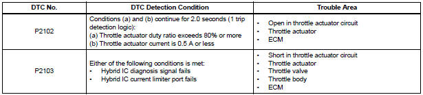
The ECM monitors the electrical current through the electronic actuator, and detects malfunctions and open circuits in the throttle actuator based on this value. If the current is outside the standard range, the ECM determines that there is a malfunction in the throttle actuator. In addition, if the throttle valve does not function properly (for example, stuck on), the ECM determines that there is a malfunction. The ECM then illuminates the MIL and sets a DTC.
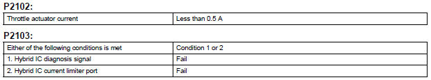
Example: When the electrical current is more than 10 A, or less than 0.5 A and the throttle actuator duty ratio exceeds 80%, the ECM interprets this as the current being outside the standard range, and illuminates the MIL and sets a DTC.
If the malfunction is not repaired successfully, a DTC is set when the engine is quickly revved up to a high rpm several times after the engine has idled for 5 seconds after engine start.
MONITOR STRATEGY
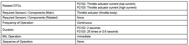
TYPICAL ENABLING CONDITIONS

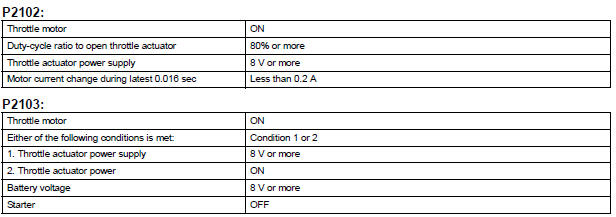
TYPICAL MALFUNCTION THRESHOLDS
FAIL-SAFE
When either of these DTCs, as well as other DTCs relating to ETCS (Electronic Throttle Control System) malfunctions, is set, the ECM enters fail-safe mode. During fail-safe mode, the ECM cuts the current to the throttle actuator off, and the throttle valve is returned to a 6° throttle angle by the return spring. The ECM then adjusts the engine output by controlling the fuel injection (intermittent fuel-cut) and ignition timing, in accordance with the accelerator pedal opening angle, to allow the vehicle to continue at a minimal speed.
If the accelerator pedal is depressed gently, the vehicle can be driven slowly.
Fail-safe mode continues until a pass condition is detected, and the ignition switch is then turned off.
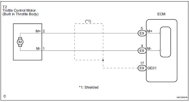
WIRING DIAGRAM
INSPECTION PROCEDURE
HINT:
- Read freeze frame data using the intelligent tester. The ECM records vehicle and driving condition information as freeze frame data the moment a DTC is stored. When troubleshooting, freeze frame data can be helpful in determining whether the vehicle was running or stopped, whether the engine was warmed up or not, whether the air-fuel ratio was lean or rich, as well as other data recorded at the time of a malfunction.
- The throttle actuator current (THROTTLE MOT) and the throttle actuator duty ratio (THROTTLE OPN / THROTTLE CLS) can be read using the intelligent tester. However, the ECM shuts off the throttle actuator current when the ETCS malfunctions.
1 INSPECT THROTTLE BODY (RESISTANCE OF THROTTLE CONTROL MOTOR)
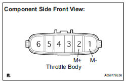
(a) Disconnect the T2 throttle body connector.
(b) Measure the resistance according to the value(s) in the table below.
Standard resistance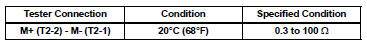
(c) Reconnect the throttle body connector.

2 CHECK HARNESS AND CONNECTOR (THROTTLE CONTROL MOTOR - ECM)
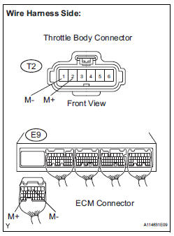
(a) Disconnect the T2 throttle body connector.
(b) Disconnect the E9 ECM connector.
(c) Measure the resistance according to the value(s) in the table below.
Standard resistance : 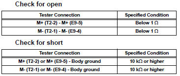
(d) Reconnect the throttle body connector.
(e) Reconnect the ECM connector.

3 INSPECT THROTTLE BODY
(a) Check for foreign objects between the throttle valve and the housing.
OK: Normal

4 INSPECT THROTTLE VALVE
(a) Check if the throttle valve opens and closes smoothly.
OK: The throttle valve opens and closes smoothly.

REPLACE ECM (See page ES-498)
 Transmission Range Sensor Circuit Malfunction (PRNDL Input)
DESCRIPTION
The park/neutral position switch detects the shift lever position and sends
signals to the ECM.
HINT:
After confirming DTC P0705, use the intelligent tester to confirm the PN ...
 Throttle Actuator Control System
DESCRIPTION
The throttle actuator is operated by the ECM, and opens and closes the
throttle valve using the gears.
The opening angle of the throttle valve is detected by the Throttle Positio ...
Other materials:
Inspection
1. INSPECT CHARCOAL CANISTER ASSEMBLY
(a) Visually check the charcoal canister for cracks or
damage.
If cracks or damage are found, replace the charcoal
canister assembly.
(b) Check charcoal canister operation.
(1) With the purge port closed, blow 1.67 kPa (17.0
gf/cm2, 0.24 psi) ...
ECM
COMPONENTS
REMOVAL
1. REMOVE GLOVE COMPARTMENT DOOR ASSEMBLY
(a) Push the right side wall and then push the left wall
to release the stoppers.
(b) Pull the glove compartment door sub-assembly
rearward to remove it.
2. REMOVE NO. 2 INSTRUMENT PANEL BOX
(a) Disengage the 2 claws ...
Differential system
PRECAUTION
NOTICE:
When disconnecting the negative (-) battery terminal,
initialize the following systems after the terminal is
reconnected.
1. Before disassembly, clean the outside of the rear
differential assembly and remove any sand or mud to
prevent it from entering the inside of the as ...
