Toyota Sienna Service Manual: Vehicle Position Mark is not Updated
INSPECTION PROCEDURE
1 CHECK MAP DISC
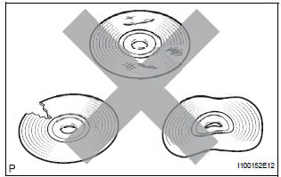
- Check that the map disc is not deformed or cracked.
OK: No deformations or cracks on map disc.
2 CHECK MAP DISPLAY
- Check if a touch scroll can be performed on the map display.
OK: Touch scroll can be performed
3 CHECK VEHICLE SENSOR (NAVIGATION CHECK MODE)
- Enter the "Navigation Check" mode (Vehicle Sensors).
- While driving the vehicle, compare the "Speed" indicator to the reading on the speedometer. Check if these readings are almost equal.
OK: The readings are almost equal.
PROCEED TO NEXT CIRCUIT INSPECTION SHOWN IN PROBLEM SYMPTOMS TABLE
 Cursor or Map Rotates when Vehicle Stopped
INSPECTION PROCEDURE
1 CHECK CONDITION
Check with the customer if the vehicle has been turned
by a turntable.
OK:
Vehicle has not been turned by turntable.
HINT:
If the vehicle is t ...
 Current Position Display does not Appear
INSPECTION PROCEDURE
1 CHECK RADIO AND NAVIGATION ASSEMBLY
Check if a map disc is inserted into the map disc slot.
OK:
A map disc is inserted
2 CHECK MAP DISC
Check that the map ...
Other materials:
Installation
1. INSTALL THROTTLE BODY
Install a new throttle body gasket to the intake air
surge tank.
Install the throttle body with the 4 bolts.
Torque: 10 N*m (102 kgf*cm, 7 ft.*lbf)
Connect the 2 water by-pass hoses.
Connect the throttle body connector and clamp.
2. ...
How to proceed with
troubleshooting
HINT:
Troubleshoot in accordance with the procedures on the
following pages.
1 VEHICLE BROUGHT TO WORKSHOP
2 DTC CHECK
Check for DTCs and make a note of the code that is
output (See page MP-14).
Delete the DTC.
Check if the DTC is output once again when the problem
symptom is simulat ...
Diagnostic trouble code chart
1. DTCS FOR OCCUPANT CLASSIFICATION SYSTEM
If a trouble code is displayed during the DTC check,
check the circuit listed for the code in the table below
(proceed to the page listed for that circuit).
HINT:
When DTC B1150/23 is detected as a result of
troubleshooting for the airbag system, pe ...
