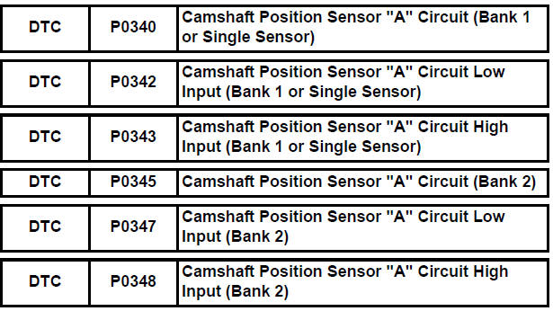
Toyota Sienna Service Manual: Camshaft Position Sensor "A" Circuit
DESCRIPTION
The intake camshaft's Variable Valve Timing (VVT) sensor (G signal) consists of a magnet and MRE (Magneto Resistance Element).
The VVT camshaft drive gear has a sensor plate with 3 teeth on its outer circumference. When the gear rotates, changes occur in the air gaps between the sensor plate and MRE, which affects the magnetic field. As a result, the resistance of the MRE material fluctuates. The VVT sensor converts the gear rotation data to pulse signals, uses the pulse signals to determine the camshaft angle, and sends it to the ECM.
The crankshaft angle sensor plate has 34 teeth. The pickup coil generates 34 signals for each engine revolution. Based on combination of the G signal and NE signal, the ECM detects the crankshaft angle.
Then the ECM uses this data to control fuel injection time and injection timing. Also, based on the NE signal, the ECM detects the engine speed.
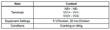
Reference: Inspection using an oscilloscope
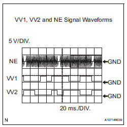
HINT:
- The correct waveform is shown in the illustration.
- VV1+ and VV2+ stand for the VVT sensor signal, and NE+ stands for the
CKP sensor signal.
MONITOR DESCRIPTION
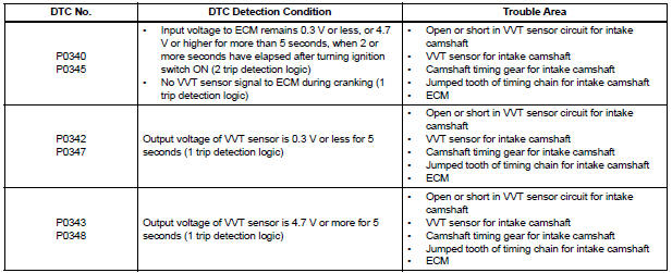
If no signal is transmitted by the VVT sensor despite the engine revolving, or the rotations of the camshaft and the crankshaft are not synchronized, the ECM interprets this as a malfunction of the sensor.
MONITOR STRATEGY
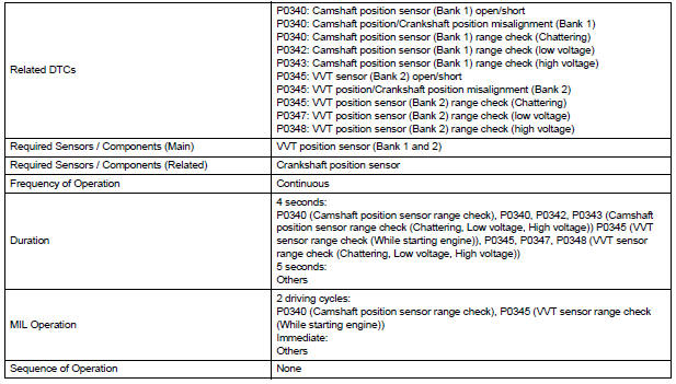
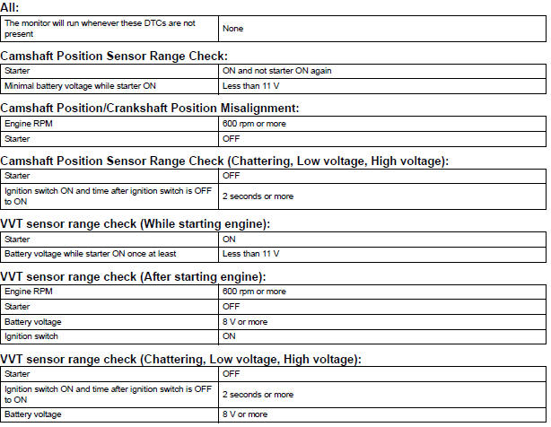
TYPICAL ENABLING CONDITIONS
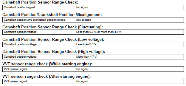
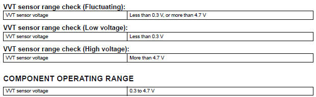
TYPICAL MALFUNCTION THRESHOLDS
WIRING DIAGRAM
Refer to DTC P0335 (See page ES-222).
INSPECTION PROCEDURE
HINT:
Read freeze frame data using the intelligent tester. The ECM records vehicle and driving condition information as freeze frame data the moment a DTC is stored. When troubleshooting, freeze frame data can be helpful in determining whether the vehicle was running or stopped, whether the engine was warmed up or not, whether the air-fuel ratio was lean or rich, as well as other data recorded at the time of a malfunction.
1 CHECK HARNESS AND CONNECTOR (SENSOR POWER SOURCE)
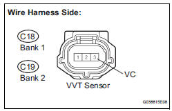
(a) Disconnect the C18 or C19 VVT sensor connector.
(b) Measure the voltage according to the value(s) in the table below.
Standard voltage 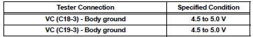
(c) Reconnect the VVT sensor connector.


2 CHECK HARNESS AND CONNECTOR (VVT SENSOR - ECM)
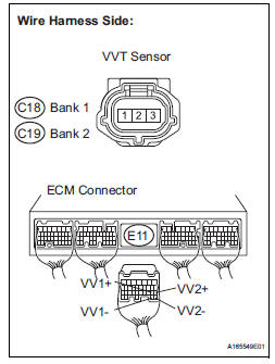
(a) Disconnect the C18 or C19 VVT sensor connector.
(b) Disconnect the E11 ECM connector.
(c) Measure the resistance according to the value(s) in the table below.
Standard resistance : 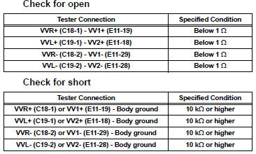
(d) Reconnect the VVT sensor connector.
(e) Reconnect the ECM connector.

3 CHECK SENSOR INSTALLATION (VVT SENSOR)
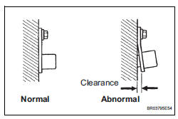
(a) Check the VVT sensor installation condition.
OK: Sensor is installed correctly.


4 CHECK CAMSHAFT TIMING GEAR ASSEMBLY (TEETH OF PLATE)
(a) Check the teeth of the signal plate.
OK: Sensor plate teeth do not have any cracks or deformation.

5 REPLACE VVT SENSOR
(a) Replace the VVT sensor (See page ES-509).

6 CHECK WHETHER DTC OUTPUT RECURS
(a) Connect the intelligent tester to the DLC3.
(b) Turn the ignition switch to the ON position.
(c) Turn the intelligent tester on.
(d) Clear the DTCs.
(e) Select the following menu items: DIAGNOSIS / ENHANCED OBD II / DTC / INFO / PENDING CODES.
(f) Read the DTCs.
Result 
HINT:
If the engine does not start, replace the ECM.

END
7 CHECK HARNESS AND CONNECTOR (VVT SENSOR - ECM)
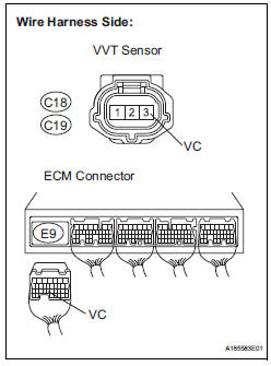
(a) Disconnect the C18 or C19 VVT sensor connector.
(b) Disconnect the E9 ECM connector.
(c) Measure the resistance according to the value(s) in the table below.
Standard resistance : 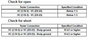
(d) Reconnect the VVT sensor connector.
(e) Reconnect the ECM connector.

REPLACE ECM (See page ES-498)
 Crankshaft Position Sensor
DESCRIPTION
The Crankshaft Position (CKP) sensor system consists of a CKP sensor plate
and a pickup coil. The
sensor plate has 34 teeth and is installed on the crankshaft. The pickup coil is
...
 Ignition Coil "A" Primary
HINT:
These DTCs indicate malfunctions relating to the primary circuit.
If DTC P0351 is set, check the No. 1 ignition coil with igniter circuit.
If DTC P0352 is set, check the No. 2 igniti ...
Other materials:
Removal
1. REMOVE FRONT WHEEL
2. REMOVE FRONT AXLE HUB LH NUT
HINT:
(See page AH-4)
SST 09930-00010
3. SEPARATE SPEED SENSOR FRONT LH
HINT:
(See page AH-4)
4. SEPARATE FRONT DISC BRAKE CALIPER
ASSEMBLY LH
HINT:
(See page AH-4)
5. REMOVE FRONT DISC
6. SEPARATE TIE ROD ASSEMBLY LH
HINT:
(See pa ...
Installation
1. INSTALL FRONT STABILIZER BAR
2. INSTALL NO. 1 FRONT STABILIZER BAR BUSHING
(a) Install the 2 front stabilizer bar bush No.1 to the
stabilizer bar front.
NOTICE:
Install the bushings with the slit facing on the
rear side of the vehicle.
HINT:
Install the bushing to the outer side of th ...
Television camera
COMPONENTS
REMOVAL
1. REMOVE BACK DOOR GARNISH CENTER
HINT:
Back Door:
Power Back Door:
2. REMOVE BACK DOOR SIDE GARNISH LH
HINT:
Back Door:
Power Back Door:
3. REMOVE BACK DOOR SIDE GARNISH RH
Back Door:
Power Back Door: ...
