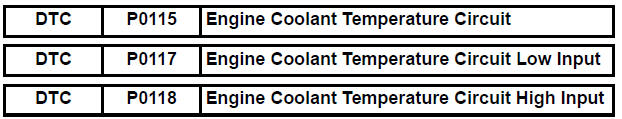
Toyota Sienna Service Manual: Engine Coolant Temperature Circuit
DESCRIPTION
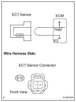
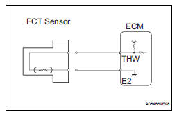
A thermistor is built into the Engine Coolant Temperature (ECT) sensor, of which the resistance value varies according to the ECT.
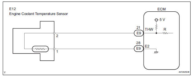
The structure of the sensor and its connection to the ECM are the same as those of the Intake Air Temperature (IAT) sensor.
HINT: When any of DTCs P0115, P0117 and P0118 are set, the ECM enters fail-safe mode. During fail-safe mode, the ECT is estimated to be 80°C (176°F) by the ECM. Fail-safe mode continues until a pass condition is detected.
HINT:
When any of these DTCs are set, check the ECT by selecting the following menu items on the intelligent tester: DIAGNOSIS / ENHANCED OBD II / DATA LIST / PRIMARY / COOLANT TEMP.
MONITOR DESCRIPTION
The Engine Coolant Temperature (ECT) sensor is used to monitor the ECT. The ECT sensor has a thermistor with a resistance that varies according to the temperature of the engine coolant. When the coolant temperature becomes low, the resistance in the thermistor increases. When the temperature becomes high, the resistance drops.
These variations in resistance are reflected in the voltage output from the sensor. The ECM monitors the sensor voltage and uses this value to calculate the ECT. When the sensor output voltage deviates from the normal operating range, the ECM interprets this as a fault in the ECT sensor and sets a DTC.
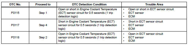
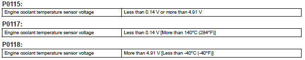
Example: If the sensor voltage output is -40°C (-40°F) for 0.5 seconds or more, the ECM determines that there is an open in the ECT sensor circuit, and sets DTC P0118. Conversely, if the voltage output is more than 140°C (284°F) for 0.5 seconds or more, the ECM determines that there is a short in the sensor circuit, and sets DTC P0117.
If the malfunction is not repaired successfully, a DTC is set 0.5 seconds after the engine is next started.
MONITOR STRATEGY

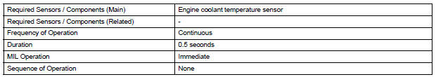
TYPICAL ENABLING CONDITIONS

TYPICAL MALFUNCTION THRESHOLDS
COMPONENT OPERATING RANGE

WIRING DIAGRAM
INSPECTION PROCEDURE
HINT:
- If other DTCs relating to different systems that have terminal E2 as the ground terminal are output simultaneously, terminal E2 may have an open circuit.
- Read freeze frame data using the intelligent tester. The ECM records vehicle and driving condition information as freeze frame data the moment a DTC is stored. When troubleshooting, freeze frame data can be helpful in determining whether the vehicle was running or stopped, whether the engine was warmed up or not, whether the air-fuel ratio was lean or rich, as well as other data recorded at the time of a malfunction.
1 READ VALUE OF INTELLIGENT TESTER (ENGINE COOLANT TEMPERATURE)
(a) Connect the intelligent tester to the DLC3.
(b) Turn the ignition switch to the ON position.
(c) Turn the tester on.
(d) Select the following menu items: DIAGNOSIS / ENHANCED OBD II / DATA LIST / PRIMARY / COOLANT TEMP.
(e) Read the value displayed on the tester.
Standard: Between 80°C and 97°C (176°F and 207°F) with warm engine.
Result 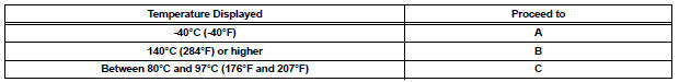
HINT:
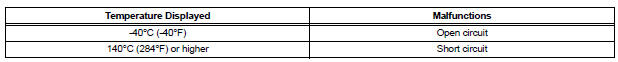
- If there is an open circuit, the intelligent tester indicates -40°C (-40°F).
- If there is a short circuit, the intelligent tester indicates 140°C (284°F) or higher.

2 READ VALUE OF INTELLIGENT TESTER (CHECK FOR OPEN IN WIRE HARNESS)
(a) Disconnect the E12 Engine Coolant Temperature (ECT) sensor connector.
(b) Connect terminals 1 and 2 of the ECT sensor connector on the wire harness side.
(c) Connect the intelligent tester to the DLC3.
(d) Turn the ignition switch to the ON position.
(e) Turn the tester on.
(f) Select the following menu items: DIAGNOSIS / ENHANCED OBD II / DATA LIST / PRIMARY / COOLANT TEMP.
(g) Read the value displayed on the tester.
Standard: 140°C (284°F) or higher
(h) Reconnect the ECT sensor connector.

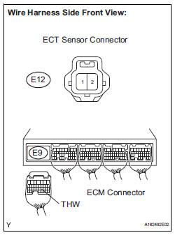
3 CHECK HARNESS AND CONNECTOR (ENGINE COOLANT TEMPERATURE SENSOR - ECM)
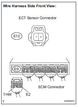
(a) Disconnect the E12 ECT sensor connector.
(b) Disconnect the E9 ECM connector.
(c) Measure the resistance according to the value(s) in the table below.
Standard resistance 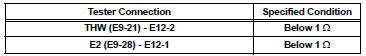
(d) Reconnect the ECM connector.
(e) Reconnect the ECT connector.

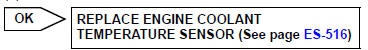
REPLACE ECM (See page ES-498)
4 READ VALUE OF INTELLIGENT TESTER (CHECK FOR SHORT IN WIRE HARNESS)
(a) Disconnect the E12 ECT sensor connector.
(b) Connect the intelligent tester to the DLC3.
(c) Turn the ignition switch to the ON position.
(d) Turn the tester on.
(e) Select the following menu items: DIAGNOSIS / ENHANCED OBD II / DATA LIST / PRIMARY / COOLANT TEMP.
(f) Read the value displayed on the tester.
Standard: -40°C (-40°F)
(g) Reconnect the ECT sensor connector.

5 CHECK HARNESS AND CONNECTOR (ENGINE COOLANT TEMPERATURE SENSOR - ECM)
(a) Disconnect the E12 ECT sensor connector.
(b) Disconnect the E9 ECM connector.
(c) Measure the resistance according to the value(s) in the table below.
Standard resistance 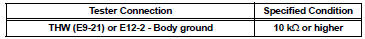
(d) Reconnect the ECT sensor connector.
(e) Reconnect the ECM connector.

REPLACE ECM (See page ES-498)
 Intake Air Temperature Sensor Gradient Too High
DESCRIPTION
The Intake Air Temperature (IAT) sensor, mounted on the Mass Air Flow (MAF)
meter, monitors the IAT.
The IAT sensor has a built-in thermistor with a resistance that varies ac ...
 Engine Coolant Temperature Circuit Range / Performance Problem
DESCRIPTION
Refer to DTC P0115 (See page ES-133).
MONITOR DESCRIPTION
The ECT sensor is used to monitor the ECT. The ECT sensor has a built-in
thermistor with a resistance
that varies ac ...
Other materials:
Short to GND in Driver Side Squib Circuit
DTC B0102/11 Short to GND in Driver Side Squib Circuit
DESCRIPTION
The driver side squib circuit consists of the center airbag sensor assembly,
the spiral cable and the
steering pad.
The circuit instructs the SRS to deploy when deployment conditions are met.
DTC B0102/11 is recorded when ...
Power mirror control system (w/o Memory)
PARTS LOCATION
Problem symptoms table
POWER MIRROR CONTROL SYSTEM
Symptom
Suspected area
Mirror does not operate
Outer mirror switch assembly
Outer rear view mirror assembly
Wire harness
Mirror operates abnormally
O ...
Power back door touch sensor
INSPECTION
1. INSPECT POWER BACK DOOR TOUCH SENSOR LH
Check the resistance of the sensor.
Resistance
If the result is not as specified, replace the sensor.
2. INSPECT POWER BACK DOOR TOUCH SENSOR RH
Check the resistance of the sensor.
Resistance
If the result is not as ...
