Toyota Sienna Service Manual: Radio Broadcast cannot be Received or Poor Reception
INSPECTION PROCEDURE
1 CHECK RADIO AND NAVIGATION ASSEMBLY
- Check the radio's automatic station search function.
- Check the radio's automatic station search function by activating it.
OK: The radio's automatic station search function works properly.
2 INSPECT RADIO AND NAVIGATION ASSEMBLY
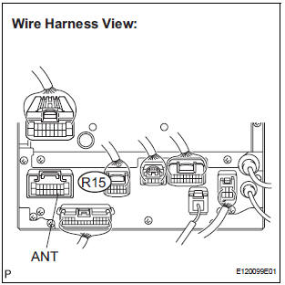
- Disconnect the radio and navigation assembly connector R15.
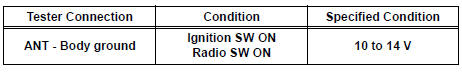
- Measure the voltage according to the value(s) in the table below.
Standard voltage
3 CHECK OPTIONAL COMPONENTS
- Check optional components (sun-shade film, telephone antenna, etc.).
- Check if any optional components, such as sunshade film or telephone antenna that may decrease reception capacity, are installed.
OK: Optional components are installed.
NOTICE: Do not remove any optional components installed by the customer without his or her consent
4 CHECK RADIO AND NAVIGATION ASSEMBLY
- Preparation for check
- Remove the antenna plug from the radio and navigation assembly.
- Check for noise
- Turn the ignition switch to the ACC position with the radio and navigation assembly connector connected.
- Turn the radio on and put into AM mode.
- Place a screwdriver, thin wire, or other metal object on the radio receiver's antenna jack and check that noise can be heard from the speaker.
OK: Noise occurs
5 CHECK GLASS ANTENNA
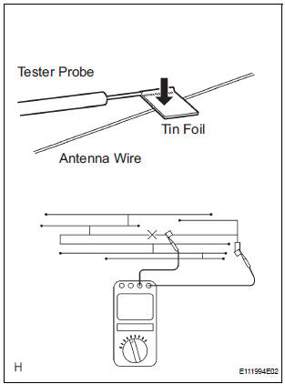
- Check for continuity of the antenna.
HINT: Check for continuity at the center of each antenna wire as shown in the illustration.
NOTICE: When cleaning the glass, wipe it in the direction of the wire with a soft dry cloth. Take care not to damage the wire. Do not use detergents or glass cleaners with abrasive ingredients. When measuring voltage, wrap a piece of tin foil around the tip of the negative probe and press the foil against the wire with your finger, as shown in the illustration.
OK: There is continuity in the antenna.
6 REPLACE ANTENNA AMPLIFIER
- Replace the antenna amplifier and check that it operates normally.
OK: The antenna amplifier operates normally
REPLACE RADIO AND NAVIGATION ASSEMBLY
 CD Sound Skips
INSPECTION PROCEDURE
1 CHECK CD
Check the CD.
OK:
The CD is clean.
HINT:
If dirt is on the CD surface, wipe it clean with a soft cloth
from the inside to the outside in a radial directio ...
 Illumination for Panel Switch does not Come on with Tail Switch ON
INSPECTION PROCEDURE
1 CHECK VEHICLE SIGNAL (DISPLAY CHECK MODE)
Enter the "Display Check" mode (Vehicle Signal Check Mode).
Check that the display changes between ON and OF ...
Other materials:
Air Mix Damper Position Sensor Circuit (Passenger Side)
DESCRIPTION
This sensor detects the position of the air mix control servo motor (air mix
damper) and sends the
appropriate signals to the A/C amplifier. The position sensor is built in the
air mix control servo motor. The
position sensor's resistance changes as the air mix control servo m ...
Diagnosis system
1. CHECK DLC3
The vehicle's ECU uses ISO 15765-4 for
communication protocol. The terminal arrangement
of the DLC3 complies with SAE J1962 and matches
the ISO 15765-4 format.
NOTICE:
*: Before measuring the resistance, leave the
vehicle as is for at least 1 minute and do not
...
Folding down the third seats (manual seats)
Before folding the third seats
Fold the outside head
restraints and lower the center
head restraint to the lowest
position , and
stow the seat belt buckles.
Stow the center seat belt.
Folding down the third seatbacks
Pull the “TO FOLD/LIFT SEATBACK”
strap a
Return ...
