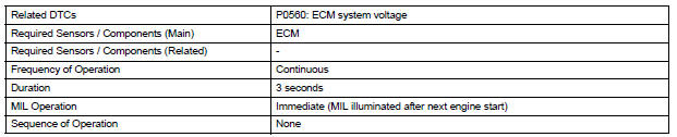
Toyota Sienna Service Manual: System Voltage

MONITOR DESCRIPTION
The battery supplies electricity to the ECM even when the ignition switch is off. This power allows the ECM to store data such as DTC history, freeze frame data and fuel trim values. If the battery voltage falls below a minimum level, these memories are cleared and the ECM determines that there is a malfunction in the power supply circuit. When the engine is next started, the ECM illuminates the MIL and sets the DTC.

HINT:
If DTC P0560 is set, the ECM does not store other DTCs.
MONITOR STRATEGY
TYPICAL ENABLING CONDITIONS

TYPICAL MALFUNCTION THRESHOLDS

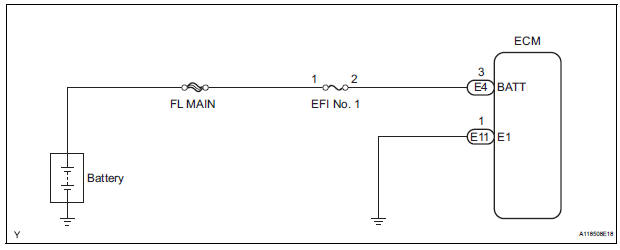
WIRING DIAGRAM
INSPECTION PROCEDURE
HINT:
Read freeze frame data using the intelligent tester. The ECM records vehicle and driving condition information as freeze frame data the moment a DTC is stored. When troubleshooting, freeze frame data can be helpful in determining whether the vehicle was running or stopped, whether the engine was warmed up or not, whether the air-fuel ratio was lean or rich, as well as other data recorded at the time of a malfunction.
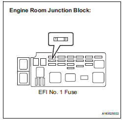
1 CHECK FUSE (EFI NO. 1 FUSE)
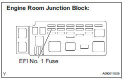
(a) Remove the EFI No. 1 fuse from the engine room junction block.
(b) Measure the resistance according to the value(s) in the table below.
Standard resistance: Below 1 Ω
(c) Reinstall the EFI No. 1 fuse.


2 INSPECT ECM (BATT VOLTAGE)
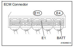
(a) Measure the voltage according to the value(s) in the table below.
Standard voltage 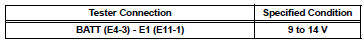


REPLACE ECM (See page ES-498)
3 CHECK HARNESS AND CONNECTOR (ECM - EFI NO. 1 FUSE)
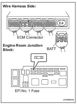
(a) Check the harness and the connector between the EFI No. 1 fuse and ECM.
(1) Remove the EFI No. 1 fuse from the engine room junction block.
(2) Disconnect the E4 ECM connector.
(3) Measure the resistance according to the value(s) in the table below.
Standard resistance : 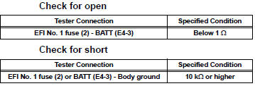
(4) Reconnect the ECM connector.
(5) Reinstall the EFI No. 1 fuse.

4 CHECK HARNESS AND CONNECTOR (EFI NO. 1 FUSE - BATTERY)
(a) Check the harness and the connector between the EFI No. 1 fuse and battery.
(1) Remove the EFI No. 1 fuse from the engine room junction block.
(2) Disconnect the negative battery cable.
(3) Measure the resistance according to the value(s) in the table below.
Standard resistance: 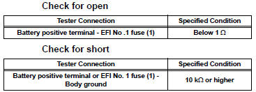
(4) Reconnect the negative battery cable.
(5) Reinstall the EFI No. 1 fuse

5 INSPECT BATTERY
(a) Check that the battery is not depleted.

CHECK AND REPLACE ENGINE ROOM RELAY BLOCK
 Cold Start Ignition Timing Performance
DESCRIPTION
This monitor will run when the engine is started at -10 to 50ô¯C (14 to 122ô¯F)
of the engine coolant
temperature. The DTC will set after the engine idling for 13 seconds (2 trip
...
 Internal Control Module Random Access Memory (RAM) Error
DESCRIPTION
The ECM continuously monitors its own internal memory status, internal
circuits, and output signals
transmitted to the throttle actuator. This self-check ensures that the ECM is
...
Other materials:
Locking and unlocking the back door
Entry function (vehicles with a smart key system)
Carry the electronic key to enable this function.
Press the unlock button to
unlock all the doors.
The door cannot be unlocked for
3 seconds after the door is
locked.
Lock the back door again when
you leave the vehicle. The back
...
Editing the contact data
For PBAP compatible BluetoothôÛ phones, this function is available when
ãAutomatic Transferã is set to off.
Select ãEdit Contactã.
Select the desired contact.
Select corresponding to the
desired name or number.
For editing the name
Follow the steps in ãRegisterin ...
Disassembly
1. REMOVE RH SEAT REAR SEAT RECLINING COVER
Remove the 2 screws.
Remove the RH seat rear seat reclining cover by
pulling it out in the arrow mark direction shown in
the illustration.
2. REMOVE LH SEAT REAR SEAT RECLINING COVER
Remove the 2 screws.
R ...
