Toyota Sienna Service Manual: Cold Start Ignition Timing Performance

DESCRIPTION
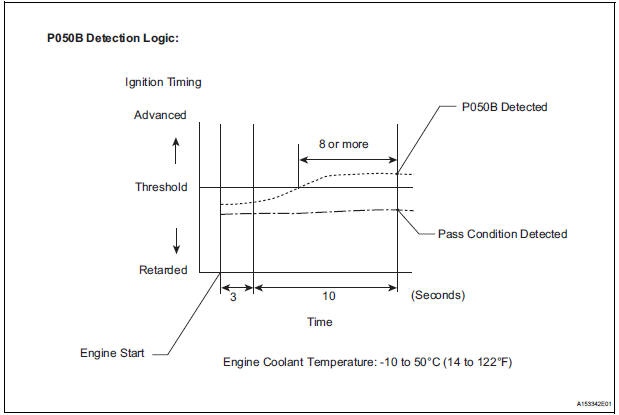
This monitor will run when the engine is started at -10 to 50°C (14 to 122°F) of the engine coolant temperature. The DTC will set after the engine idling for 13 seconds (2 trip detection logic).
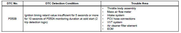
The DTC is designed to monitor the idle air control at cold start. When the engine is started at lower than 50°C (122°F) of the engine coolant temperature, the ECM measures the accumulated mass air flow at the engine idling. If it does not reach the criteria within 10 seconds, the ECM interprets this as a malfunction.
The MIL is illuminated and a DTC is set when the malfunction is detected in consecutive driving cycles (2 trip detection logic).
The ETCS (Electrical Throttle Control System) controls the idle speed. The ETCS operates the throttle actuator to open and close the throttle valve, and adjusts the intake air amount to achieve the target idle speed.
| NOTICE: When the negative battery terminal is disconnected during inspection or repairs, the ISC (Idle Speed Control) learned values are cleared. ISC learning is performed when the engine has been warmed up and idled for 5 minutes because this DTC cannot be set after the ISC learned values cleared. |
MONITOR DESCRIPTION
MONITOR STRATEGY
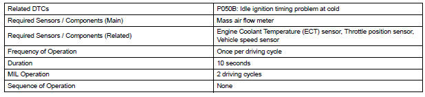
TYPICAL ENABLING CONDITIONS
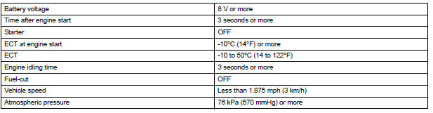
TYPICAL MALFUNCTION THRESHOLDS

INSPECTION PROCEDURE
HINT:
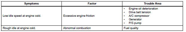
- DTC P050B may be set when the engine shows the symptom as listed below. If necessary, check the trouble area as listed below.
- Read freeze frame data using the intelligent tester. The ECM records vehicle and driving condition information as freeze frame data the moment a DTC is stored. When troubleshooting, freeze frame data can be helpful in determining whether the vehicle was running or stopped, whether the engine was warmed up or not, whether the air-fuel ratio was lean or rich, as well as other data recorded at the time of a malfunction.
1 CHECK ANY OTHER DTCS OUTPUT (IN ADDITION TO DTC P050B)
(a) Connect the intelligent tester to the DLC3.
(b) Turn the ignition switch to the ON position.
(c) Turn the tester on.
(d) Select the following the menu items: DIAGNOSIS / ENHANCED OBD II / DTC INFO / CURRENT CODES.
(e) Read the DTCs.
Result 
HINT: If any DTCs other than P050B are output, troubleshoot those DTCs first.

2 READ VALUE USING INTELLIGENT TESTER (FUEL TRIM)
HINT:
Calculate the total fuel trim values to check the characteristic deviation of the mass air flow meter.
(a) Connect the intelligent tester to the DLC3.
(b) Start the engine.
(c) Turn the tester on.
(d) Select the following menu items: DIAGNOSIS / ENHANCED OBD II / DATA LIST / PRIMARY / SHORT FT #1 and LONG FT #1.
(e) Read the values displayed on the tester at engine idles.
(f) Add together the SHORT FT #1 and LONG FT #1 values to obtain the total FUEL TRIM.
OK: Total of SHORT FT #1 and LONG FT #1 values is between -20 % and 20 %.


3 PERFORM ACTIVE TEST USING INTELLIGENT TESTER (OPERATE OCV)
(a) Connect the intelligent tester to the DLC3.
(b) Start the engine and turn the tester on.
(c) Warm up the engine.
(d) Select the following menu items: DIAGNOSIS / ENHANCED OBD II / ACTIVE TEST / VVT CTRL B1.
(e) Check the engine speed while operating the Oil Control Valve (OCV) using the tester.
OK 


4 CHECK PCV HOSE CONNECTIONS
OK: PCV hose is connected correctly and is not damaged.


5 CHECK INTAKE SYSTEM
(a) Check the intake system for vacuum leakage.
OK: No leakage from intake system.


6 CHECK AIR CLEANER FILTER ELEMENT SUB-ASSEMBLY
(a) Visually check that the air cleaner filter element is not excessively contaminated with dirt or oil.
OK: Air cleaner filter element is not excessively contaminated with dirt or oil.


7 REPLACE MASS AIR FLOW METER

8 CHECK AND REPAIR VVT SENSOR

9 REPAIR OR REPLACE PCV HOSE

10 REPAIR OR REPLACE INTAKE SYSTEM

11 REPLACE AIR CLEANER FILTER ELEMENT SUB-ASSEMBLY

12 CHECK THROTTLE VALVE

(a) Check for deposits around the throttle valve and throttle valve condition.
OK: No deposits around throttle valve and throttle valve moves smoothly.


13 REPLACE ECM

14 REPAIR OR REPLACE THROTTLE BODY ASSEMBLY

15 CHECK WHETHER DTC OUTPUT RECURS (DTC P050B)
| NOTICE: In this operation, the engine must be cold (the same level as the engine coolant temperature recorded in the freeze frame data). |
(a) Connect the intelligent tester to the DLC3.
(b) Turn the ignition switch to the ON position.
(c) Turn the tester on.
(d) Clear the DTCs.
(e) Switch the ECM from normal mode to check mode using the tester.
(f) Start the engine to idle for a minute.
OK: Stable fast idling.
(g) Read the DTCs.
OK: No DTC output.

END
 Cold Start Idle Air Control System Performance
DESCRIPTION
This monitor will run when the engine is started at -10 to 50°C (14 to 122°F)
of the engine coolant
temperature. The DTC will set after the engine idling for 13 seconds (2 trip
...
 System Voltage
MONITOR DESCRIPTION
The battery supplies electricity to the ECM even when the ignition switch is
off. This power allows the
ECM to store data such as DTC history, freeze frame data and fuel tr ...
Other materials:
Power steering fluid
Bleeding
1. BLEED POWER STEERING SYSTEM
(a) Check the fluid level (See page PS-2).
(b) Jack up the front of the vehicle and support it with
stands.
(c) Turn the steering wheel.
(1) With the engine stopped, turn the steering
wheel slowly from lock to lock several times.
(d) Lower the ...
Laser Sensor Power Source Circuit
DESCRIPTION
This circuit provides power to the laser sensor. The laser sensor emits radio
waves towards an object in
front and measures the distance and direction of the object by receiving the
beam reflections. Based on
the reflections, the sensor calculates the difference in speed between t ...
Communication Error from VSC to ECM
DTC P1630 Communication Error from VSC to ECM
DTC U0122 Lost Communication with Vehicle Dynamics
Control Module
DESCRIPTION
The skid control ECU sends signals such as cruise control cancel demand
signals and brake operation
demand (from ECM) response signals to the ECM when the dynamic laser ...
