Toyota Sienna Service Manual: Idle Control System Malfunction

DESCRIPTION
The idling speed is controlled by the ETCS (Electronic Throttle Control System). The ETCS is comprised of: 1) the one valve type throttle body; 2) the throttle actuator, which operates the throttle valve; 3) the Throttle Position (TP) sensor, which detects the opening angle of the throttle valve; 4) the Accelerator Pedal Position (APP) sensor, which detects the accelerator pedal position; and 5) the ECM, which controls the ETCS.
Based on the target idling speed, the ECM controls the throttle actuator to provide the proper throttle valve opening angle.
MONITOR DESCRIPTION
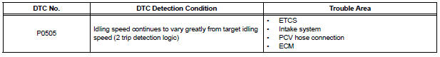
The ECM monitors the idling speed and idling air flow volume to conduct Idle Speed Control (ISC). The ECM determines that the ISC system is malfunctioning if the following conditions are met:
- The learned idling air flow volume remains at the maximum or minimum volume 5 times or more in a drive cycle.
- While driving at 6 mph (10 km/h) or more, the actual engine idling speed varies from the target idling speed by between 100 rpm and 200 rpm, 5 times or more in a drive cycle.
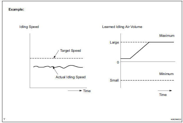
Example:
If the actual idling speed varies from the target idling speed by more than 200 rpm* 5 times in a drive cycle, the ECM illuminates the MIL and sets the DTC.
*: Threshold idling speed varies according to the engine load.
MONITOR STRATEGY
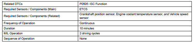
TYPICAL ENABLING CONDITIONS

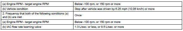
TYPICAL MALFUNCTION THRESHOLDS

INSPECTION PROCEDURE
HINT:
- The following conditions may also cause DTC P0505 to be set:
(a)The floor carpet overlapping slightly onto the accelerator pedal, causing the accelerator pedal to be slightly depressed and therefore the throttle valve position to be slightly open.
(b)The accelerator pedal being not fully released.
- Read freeze frame data using the intelligent tester. The ECM records vehicle and driving condition information as freeze frame data the moment a DTC is stored. When troubleshooting, freeze frame data can be helpful in determining whether the vehicle was running or stopped, whether the engine was warmed up or not, whether the air-fuel ratio was lean or rich, as well as other data recorded at the time of a malfunction.
1 CHECK ANY OTHER DTCS OUTPUT (IN ADDITION TO DTC P0505)
(a) Connect the intelligent tester to the DLC3.
(b) Turn the ignition switch to the ON position.
(c) Turn the tester on.
(d) Select the following menu items: DIAGNOSIS / ENHANCED OBD II / DTC INFO / CURRENT CODES.
(e) Read the DTCs.
Result 
HINT: If any DTCs other than P0505 are output, troubleshoot those DTCs first.


2 CHECK PCV HOSE CONNECTIONS
OK: PCV hose is connected correctly and is not damaged.


3 CHECK INTAKE SYSTEM
(a) Check the intake system for vacuum leakage.
OK: No leakage from intake system.


4 CHECK THROTTLE VALVE
(a) Check the throttle valve condition.
OK: No foreign objects between the throttle valve and housing.

REPLACE ECM (See page ES-498)
 Brake Switch
DESCRIPTION
The stop light switch is a duplex system that transmits two signals: STP and
ST1-. These two signals are
used by the ECM to monitor whether or not the brake system is working prope ...
 Cold Start Idle Air Control System Performance
DESCRIPTION
This monitor will run when the engine is started at -10 to 50°C (14 to 122°F)
of the engine coolant
temperature. The DTC will set after the engine idling for 13 seconds (2 trip
...
Other materials:
Reassembly
1. BEARING POSITION
2. INSTALL DIFFERENTIAL GEAR LUBE APPLY TUBE
(a) Install the differential gear lube apply tube and
transaxle apply tube clamp with the bolt to the
transaxle housing.
Torque: 9.8 N*m (100 kgf*cm, 87 in.*lbf)
NOTICE:
Make sure to insert the pipe to the s ...
On-vehicle inspection
1. INSPECT OCCUPANT CLASSIFICATION ECU
(VEHICLE NOT INVOLVED IN COLLISION)
Perform a diagnostic system check.
2. INSPECT OCCUPANT CLASSIFICATION ECU
(VEHICLE INVOLVED IN COLLISION)
Perform a diagnostic system check.
Even if the airbag was not deployed, check if there
is ...
When servicing full-time 4wd vehicles
The full-time 4WD SIENNA is equipped with the open
center differential system.
If incorrect preparations or test procedures are used, the
test will not only be unsuccessful, but may be dangerous
as well.
Therefore, before beginning any such servicing or test,
be sure to check the following ...
