Toyota Sienna: manuals and technical data
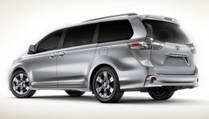
Buyers looking for a smart choice in the minivan segment will undoubtedly find themselves considering the Toyota Sienna. Since its introduction in 1998, the Sienna has won over families with its versatility, features, safety record and reputation for reliability. In reviews, we've lauded the Sienna for its smooth, refined ride and easy-to-drive nature. Another plus is that Toyota has generally offered all-wheel drive on the Sienna, making it a more practical alternative to large three-row crossover SUVs. More recent Siennas can be downright plush in higher trim levels, and there's even an SE model with a sport-tuned suspension that's genuinely sporty. Whichever version you choose, you'll be getting one of the most dependable and rewarding minivans on the market.... Here you can find Toyota Sienna owners and service manuals, electric wire diagrams and other information of car.
Toyota Sienna Service Manual
- Introduction
- Service specifications
- Maintenance
- Engine
- U151e automatic transaxle
- Transfer
- Propeller shaft
- Drive shaft
- Differential
- Axle
- Suspension
- Tire and wheel
- Brake control
- Parking brake
- Steering Column
- Power steering
- Air conditioning
- Supplemental restraint system
- Seat belt
- Theft deterrent
- Engine immobiliser
- Cruise control
- Lighting
- Wiper and washer
- Door lock
- Meter
- Audio / visual
- Navigation
- Park assist / monitoring
- Horn
- Garage door opener
- 2GR-FE Engine control system
- Supplemental restraint system
- Other system
- Windshield / windowglass
- Mirror
- Instrument panel
- Seat belt
- Seat
- Engine hood / door
- Exterior
- Interior
- Sliding roof
- Multiplex communication
- Can communication
